
Adding a TIN Surface will save you a lot of time by eliminating the task of manually adding cross-section Station and Elevation data. Once your TIN is added as a background layer, you simply add reaches over the top of the map. Then add cross-sections along the reach just like you would without a TIN. Once your sections are added, their Station & Elevation data will automatically be populated with the data connected to the TIN Surface. You will still need to add other data such as Bank Stations and Manning’s n-values however, but much of the heavy lifting is done.
When adding Sections, the software will detect the TIN Surface below the Section Line and will calculate Stations and Elevations along the Section path. In other words, a cross-section point is generated at each point where the Section Line crosses or intersects a triangle in the TIN Surface.
General Procedure For Adding a TIN Surface
1. Add the TIN Surafce as a background.
2. Draw your reach(es) over the channel. Does not need to be perfect but take your time. Once the reaches are drawn, save your project. The TIN will become embedded in the .chs project file.
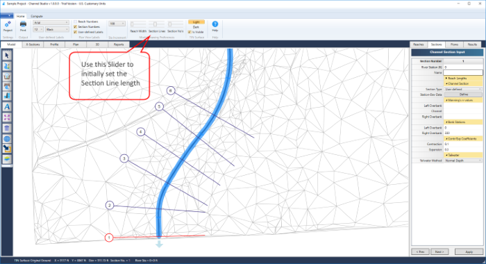
3. Add cross-sections where appropriate (starting downstream working upstream). Initially adjust the section line span using the Slider bar so that the section lines span the channel from top of bank to top of bank, plus or minus. This can be adjusted afterwards. See discussion below. Also use the Station Increment feature to lock in the locations to the nearest X feet (m). Save your project file.
4. Add your section data. Click on the X-Sections tab as well as the Sections input tab. Start at Section 1 (downstream) by clicking on Section 1 on the Section List. The Stations and Reach Lengths should already be set. You only need to add the n-values and overbank stations at this step.
Enter Manning’s n-values for the Left Overbank, Channel and Right Overbank. After Section 1, just click on the Left Overbank n-value and the software will insert the previous section’s data as the default. Tab through the Channel and Right Overbank n-values to use the defaults.
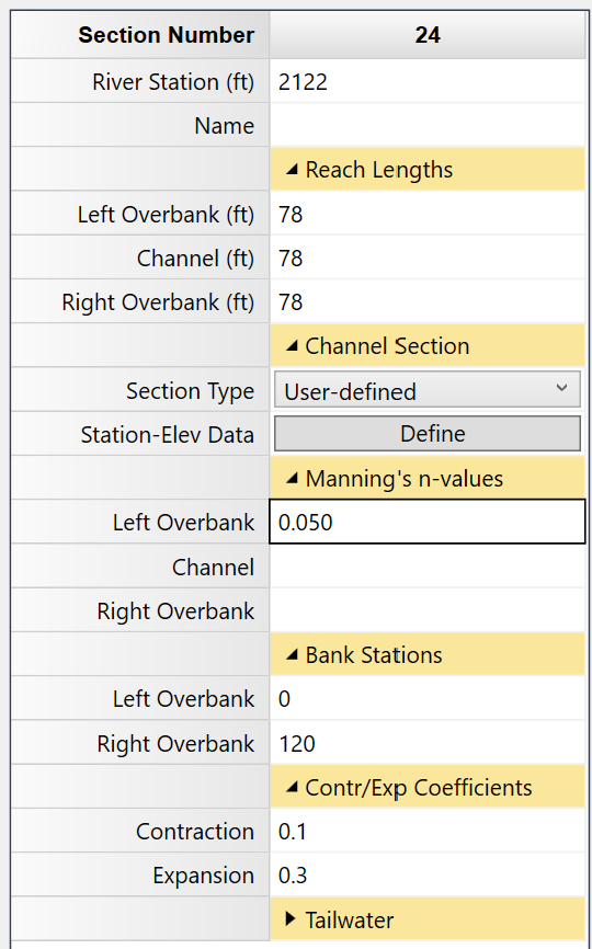
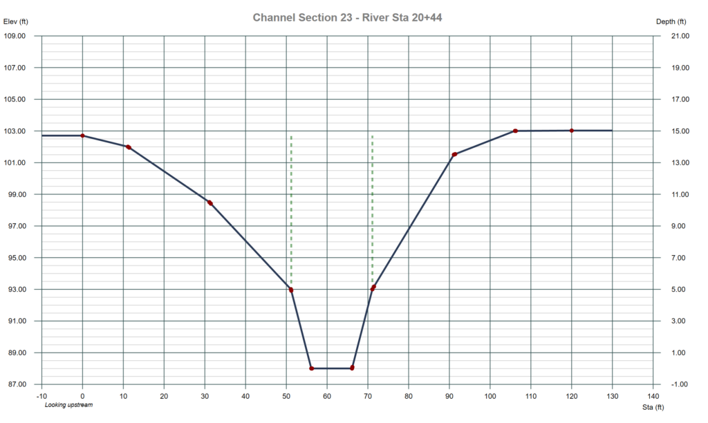
Next, set the Bank Stations. Bank Stations must coincide with a station data point on the cross-section. When working with TIN surfaces it is highly recommended to set these graphically by using the LOB and ROB controls at the top the X-Section Plot. Just click on the arrows to move the bank stations as needed.

The Bank Stations are indicated by a vertical dotted green line and will move right or left as you click the [<] or [>] buttons.
Select the next upstream section and repeat this step for the remaing sections, adding n-values and setting bank stations. Again, save your file.
5. Add your flows and set the Tailwater.
6. Compute. Recommend using the Auto Overbank Reach Length feature.
Section Line Span
The total span of the cross-section line determines the extents of the data used to describe it. You can initially adjust the span of the Section Line by adjusting the Section Line Length Slider Bar. Don’t worry too much about whether it is too short or too long. You’ll have ample opportunities to adjust later on.
Once your reach and cross-sections have added, you can inspect the cross-section data by clicking on the X-Sections tab as shown below. It is also recommended that you view the actual data for each section by clicking on the [Define] button in the data input grid. You may need to remove any duplicate data points.
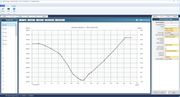
From here you can simply add the remaining required data such as Bank Stations, corresponding n-values, etc.
How to Adjust the Section Span
There may be occasions when you’ll want to either lengthen or shorten the total span of the section line. When modeling a floodplain you’ll want to be sure the section line is long enough to span the floodplain. Keep in mind that the cross-sections are limited to 250 Station/Elevation points so it is best to keep the span length only as long as needed.
There are two methods for adjusting the section lengths:
1. Use the section editing tool at the top of the X-Sections screen

Click the Up/Down arrows to expand or contract the section. Each click expands or reduces the length by 10 percent.
2. Edit the section on the Model tab
Return to the Model tab and double-click the section you wish to modify. A cross-hair cursor will appear. Now simply expand or contract the section line by using your mouse wheel. The section’s data points will update immediately. Press [Esc] or click the Ok/Select button on the top of the side toolbar when finished.
Overriding the TIN Surface
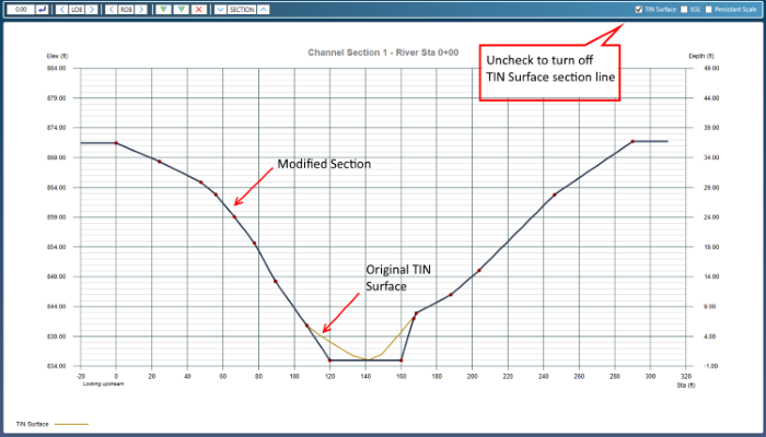
Channel Studio allows you to make modifications to your TIN-based cross-sections. This can be very useful when proposing modifications to an existing channel. Once your section has been edited, the software will plot both TIN and modified sections on the X-Sections tab.
TIN Surface Section Types are automatically assigned “User-Defined”. Their data can be viewed and edited just like any other User-defined section. To do this, click the [Define] button on the Sections input tab on the right of your screen. Then make any edits to the cross-section data and click [Ok].
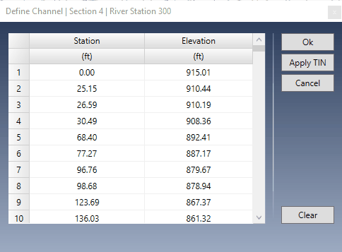
If you wish to revert back to the original TIN Surface data, click the [Apply TIN] button. This will re-apply the TIN Surface data to your cross-section.
Exporting a TIN Surface
Channel Studio can also create a TIN Surface of your finished Model. See Plan Drawings for more information.
Removing the TIN Surface
You can remove the TIN Surface from your project at any time by clicking the Add TIN Surface button on the Model tab. You will be prompted to accept.

All Reach and Cross-section data will be preserved and you can continue with modeling. You may also add the TIN back at any time and simply pick up where you left off. But again, any modified sections will revert to the TIN Surface.