After finalizing the layout of your river model, you can proceed to input data for each cross-section. The channel sections are defined by indicating the X, Y, or Station coordinates, along with elevation points from left to right when viewed upstream. This information will be referred to as “Geometric Data” in the following sections of this document.
To add section data, first click the X-Sections tab on the left and the Sections tab on the right, as shown below. Sections can be selected by clicking on the Section List to the left. Once selected, the data grid on the right side of your screen will populate with the current data.

To enter data, type in the value or select from a drop-down input box, and press [Enter] or the [Tab] key. Once the data is input, click [Apply]. Repeat these steps for each section. Use the [< Prev] and [Next >] buttons to navigate downstream to upstream.
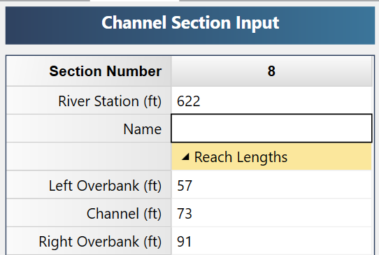
Below shows an example of cross-section data.
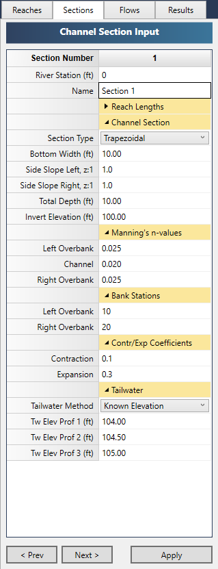
While entering data for the first time, the canvas will automatically display help diagrams to assist in your data entry.
River Station
The initial River Station is always set from the Model view when you first add your sections. However, you can directly edit this on the input grid for better specificity if needed.
Section Name
Optional but it is a recommended input. Enter any alphanumeric name.
Setting Reach Lengths
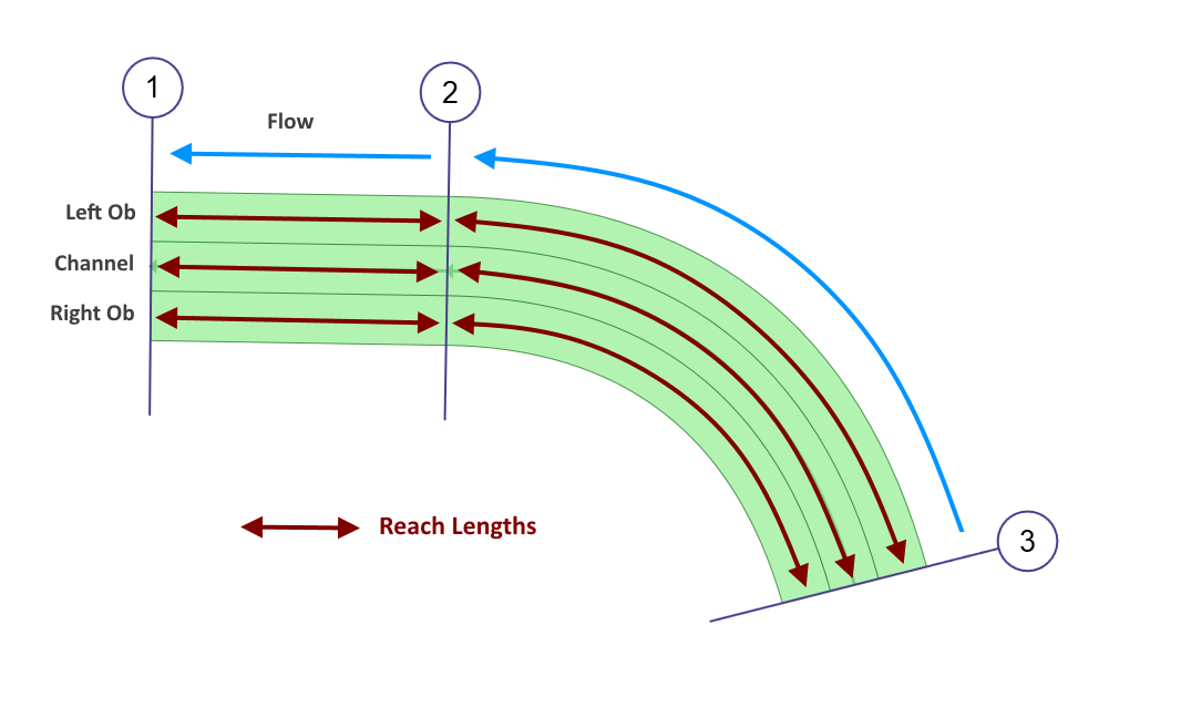
There are three unique reach lengths you can enter. One for the Left and Right Overbanks and one for the Channel portion of each section. These reach lengths are separate from the River Station and should refer to the actual distance the water travels along their respective paths. These paths are indicated by your stationing inputs for the Left and Right Overbank Stations described later.

For example, the cross-section image above and plan view below shows a channel with Left Overbank, Channel and Right Overbank. While these distances are the same between Sections 1 & 2, they vary between Sections 2 & 3 because the channel is curved. The Left Overbank distance is longer than the Channel. The Channel Reach length is longer than the Right Overbank reach length. In some cases, the Channel portion may meander, causing the Channel Reach to be the greatest.
 Initially, the program automatically enters equal reach lengths based on the Station difference between sections when you add sections to the model. These are the defaults. It is here that you can override that either by direct entry or by using Channel Studio’s “Auto Overbank Reach Length” feature. More about this feature below.
Note that if you return to the Model tab and graphically edit the locations of the sections, the program will again enter default reach lengths and you’ll need to make any necessary adjustments.
For most uniformly-shaped cross-sections, the defaults will suffice. Reach lengths are not required for Section 1 and the category will be hidden on the Sections input tab.
Auto Overbank Reach Length
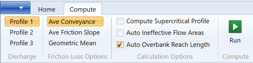
This is an optional feature that you can turn On or Off on the Compute tab.
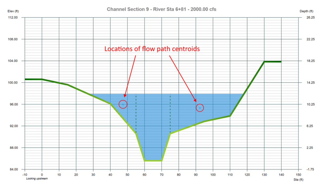
Channel Studio can dynamically calculate Left and Right Overbank Reach Lengths. Traditionally, overbank reach lengths have been measured along the “anticipated” path of the center of mass of the overbank flow. In other words the User would have to guess at the position of the flow path along the overbanks, and then derive a reach length from that. What’s worse is that this flow path varies with varying flow rates. Different flow rates generate different flow paths. More guesswork.
Channel Studio has eliminated this guesswork. It will calculate where the flow path aligns, per the centroid of the actual flow, and compute the associated reach lengths. It’s dynamic and fully automated and takes place during the water surface profile calculations. This feature can be activated or deactivated on the Compute tab.
How Auto Overbank Reach Length Works
As mentioned earlier, the program will automatically input equal reach lengths based on the Station difference between sections when you add cross-sections to your model. You can simply leave those overbank reach lengths as they are. They will be substituted with the actual overbank reach lengths during the calculations.
Prior to computing, be sure to check On the Auto Overbank Reach Length option. After computing you will notice the original overbank reach lengths have been replaced with new. These will change with each flow profile.

The above sections are on a curved Reach. Notice the LOBs are shorter than the ROBs. Channel Studio computes the overbank distance(s) as a straight line connecting the centroids between two adjacent sections. Obviously the more cross-sections you provide, the more accurate the computed overbank reach lengths will be.
The Channel Reach is independent of this option and is automatically computed along the centerline of the Reach as drawn in your Model view.
Channel Studio will automatically replace the Left and Right Overbank Reach Lengths per the computed flow path.
In summary, if you are applying overbank n-values, just activate this feature and let Channel Studio take care of the details. Note that once computed, you may turn off this option. The current overbank reach lengths will be preserved and will not change with any subsequent profile calculations. You are free to edit them as desired.
Cross-Section Geometric Data
Channel sections are described by specifying X, Y or Station, Elevation points from left to right looking upstream. Up to 250 points can be entered for each section.
Channel Studio allows you to quickly input predefined sections, i.e., Trapezoidal, Triangular or Rectangular as well as User-Defined sections. Other options allow you to:
- Copy geometric data from one section and paste into another
- Copy the section data from the previous section
- Generate section data by interpolating between any two sections
- Horizontally flip cross-section data to convert sections looking downstream to looking upstream
- Add elevation adjustments (up or down) to a cross-section
- Graphically set the Overbank Stationing
- Graphically add ineffective flow areas
- Automatically generate geometric data from a TIN Surface
Section Type
Choose your section type, Trapezoidal or User-Defined, from the drop-down list box. Each are described below.
Trapezoidal Section
Using the Trapezoidal type you can quickly add triangular, rectangular or trapezoidal shapes with varying side slopes.
Bottom Width
Enter the bottom width of the channel. For a triangular section, enter zero.
Side Slope Left & Right (z:1)
Enter the left and right side slopes, z horizontal to 1 vertical, for the channel. Enter zero for rectangular shapes.
Total Depth
Enter the total depth to be analyzed for this section.
Invert Elevation
Enter the invert elevation of this section. This item will be automatically computed when using User-defined sections.

Once you have defined a Trapezoidal section, you can later select “User-Defined” as the section type. The program will automatically import the X, Y coordinates for this section for further modification and will convert it to a User-Defined shape.
User-Defined Section
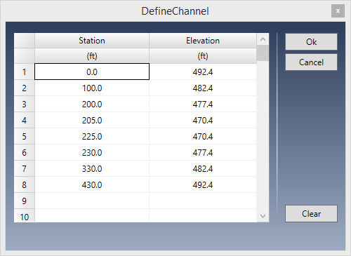
You can enter up to 250 unique Station, Elevation points to describe a channel section. Stationing should begin at zero.
 To use this channel feature, select User-defined as the Section Type from the drop-down list. Next click the [Define] button to open the User Defined Channel screen.
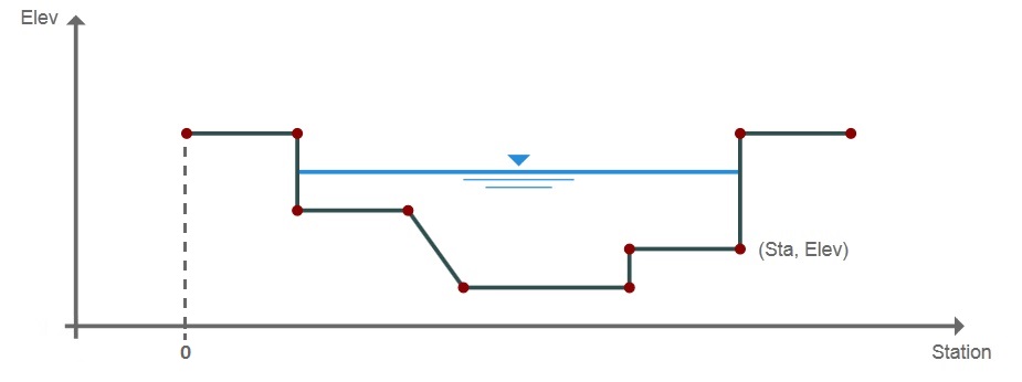
 Enter your cross-section points as looking upstream from left to right.
 A user-defined section is described by entering points containing offset stations, elevations as looking upstream from left to right.
Station
Enter the station for this point in feet or meters from the leftmost side. This is the distance from a zero baseline.
If you are pasting or entering data that does not start at zero, that’s okay.
Channel Studio will adjust them by zeroing-out the data after clicking [Ok].
Elevation
Enter the corresponding elevation for this point.
Click [Ok] when done.
Inserting and Deleting Rows
You can insert and delete rows by selecting a row and right-clicking.

Copy and Paste Data
Similarly, you can copy the entire grid to the Windows Clipboard as well as paste previously copied data, for example, from a spreadsheet.
Bank Stations and n-Values
Channel Studio employs a discharge-weighted reach length methodology when computing water surface profiles which requires unique reach lengths and roughness coefficients.
Channel Studio can divide cross-sections into three unique parts: Left Overbank, Channel and Right Overbank, each corresponds to the unique Reach Lengths described earlier. You can specify unique roughness coefficients for each as well as the offset stations that locate them along the cross-section.
Bank Stations are optional and are only used to indicate the areas corresponding to the n-values for the Left Overbank, Channel and Right Overbank. Please note that Bank Stations must coincide with an existing X, Y point describing the channel section.
In the section shown above, the Left Overbank area is between Station 0 and 200. The Channel portion is between 200 and 230. The Right Overbank is from 230 to 430. The Station of the Left Overbank is 200. The Right Overbank is 230.
Setting Bank Stations Graphically
Overbank stations can be directly entered into the input grid or can be placed graphically by using the LOB and ROB controls at the top the X-Section Plot. Just click on the arrows to move the bank stations as needed.
![]()
The Bank Stations are indicated by a vertical dotted green line.
Setting n-Values
Enter the Manning’s n-value corresponding to the Overbank and Channel portions of the section.
Now it’s time to set the flow rates that will be used to calculate your water surface profile(s).