
Channel Studio has the ability to add a Surface TIN (Triangulated Irregular Network) map to your project. This is a layer that can be added in addition to background maps. A TIN Surface can be imported from a LandXML-formatted file as well as from a .csv (comma-separated value) point-cloud file. Most CAD software supports LandXML and typically offers the option to export a TIN Surface to LandXML. If not, a simple point cloud file will do.
What is a TIN Surface?
A TIN is a vector-based representation of the physical land surface and is constructed by triangulating a set of 3-dimensional points, consisting of a Northing, Easting and Elevation. These points are connected with a series of edges to form a network of triangles. Within each triangle the surface is represented by a plane. TIN models allow extra data in complex areas and less data in non-complex areas thus making them more economical than traditional raster type DEM models.
A TIN Surface is different from a background map in that it is dynamic. That is, it will automatically generate cross-section points to match the TIN Surface. If the location of your section(s) change, so do the corresponding Station, Elevation points.
When a Surface TIN is loaded you’ll never have to enter cross-section points for your channel sections! In addition, the drawing extents will conform to the TIN Surface’s extents. Your Model canvas will be automatically geo-referenced.
How to Import a TIN Surface
TIN Surfaces are imported from the Model tab only. To import, click on the TIN Surface button on the side toolbar.
![]()
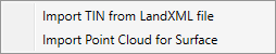
Next you’ll have the option to import either from a LandXML Surface or from a simple X, Y, Z Point file.
The status bar at the bottom of your screen will display the Surface Name as well as the TIN’s elevation at the X, Y location of your mouse.
Any existing cross-sections in your project will be updated to match the TIN Surface. New Sections added will also be attached to the TIN Surface.
Large TIN Files Can Be Slow to Draw
While most TIN Surfaces used for site design contain around 1,000 to 5,000 points, some can easily exceed 100,000. Depending on your computer’s hardware, large TIN files will require a lot of time to render and can slow down your ability to work with your project.
This becomes noticeable when the number of points exceed 5,000. Channel Studio has a set limit of points and will not load files that exceed that limit. It will provide you with a notice when that occurs. There are two things you can do to help with large TIN files:
- If it exceeds the point maximum, try to re-export the TIN Surface from your CAD software as a more simplified version with fewer points.
- Once you have opened a TIN Surface and it is displayed but slow to draw, you can hide the TIN by checking OFF the “Is Visible” property on the TIN Surface options located on the top ribbon menu.

This prevents the TIN Surface from actually being drawn but the TIN will remain fully functional behind the scenes. Turn “Is Visible” back ON from time-to-time to take a peek if desired.
Saving Projects Containing TIN Files
Channel Studio extracts only the data necessary from the TIN file and discards the rest. This data is then saved inside of your project file. It reloads the next time you open the project. There’s no need to manually manage the TIN Surface data. The original TIN .xml file remains as-is and intact.