This is typically the first thing you’ll do when creating your storm sewer plan. You can manually add and/or import up to 200 storm sewer lines to your model. There can be multiple outfalls as well.
Importing Storm Sewer Layouts and Maps
You can customize the X, Y coordinates (background extents) to match your project needs. You can also add a bitmap image or a coordinate-based map such as a DXF (Line, Polyline, Arc and Circle entities) or LandXML (Parcels, Alignments and Features) as a background to draw against.
There is a complete section that covers importing a complete layout and background maps here.
The remaining part of this article describes how to manually draw storm sewer lines to build your model.
Pan and Zoom
Stormwater Studio uses real world coordinates on its Plan. You can freely zoom in or out of your Plan, Surface or Profiles by simply scrolling your mouse wheel.
To pan, click on a clear open space on the drawing canvas and drag your mouse in any direction. Note that panning is unavailable while adding or editing Lines.
Adding New Lines & Inlets
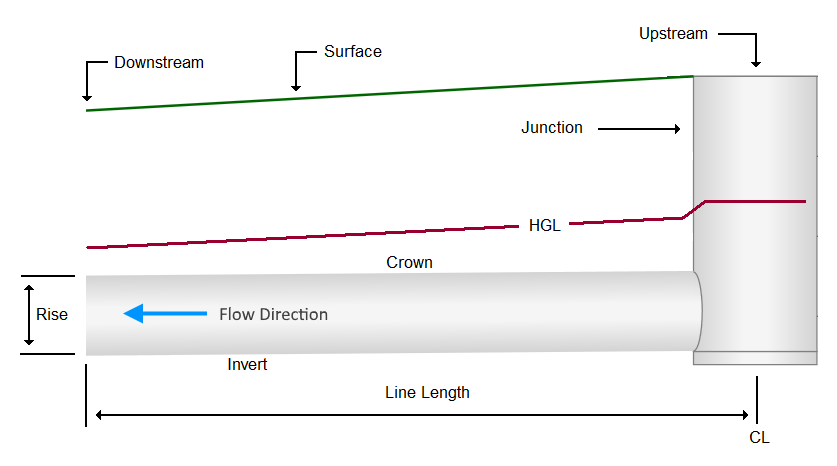
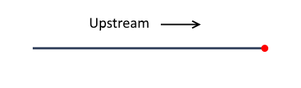
As discussed in Overview, a Line is a length of pipe with a junction (manhole, inlet, headwall, etc.) at its upstream end.
Lines can be manually added to your model by simply drawing them starting at the most downstream end and working upstream. Lines can only be added from the Plan tab or from the data input grid.
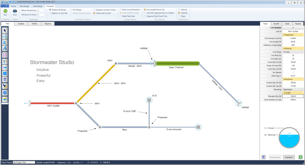
Adding (Drawing) from the Plan Tab
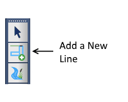
To draw a Line click on the Plan tab. To add new Lines, begin at your outfall, Line 1. Start by clicking on the [Add New Line(s)] button on the side toolbar. Remember, always draw Lines in the upstream direction.
Next, move your mouse cursor over to the drawing canvas and position it at the downstream end of the new Line. Then drag (hold down the left mouse button and move) to draw the new Line to its upstream end, i.e., desired length and deflection angle. Note that holding down the [Shift] key while dragging will lock deflection angles to whole values.
The length and angle are displayed on the input window to the right. The upstream end’s X & Y coordinates are also displayed on the status bar at the bottom. Finish the line by releasing the left mouse button. Repeat for additional Lines. Note that you can manually edit the Line’s length and angle as well as directly enter the Lines X,Y coordinates afterward to get more precise.
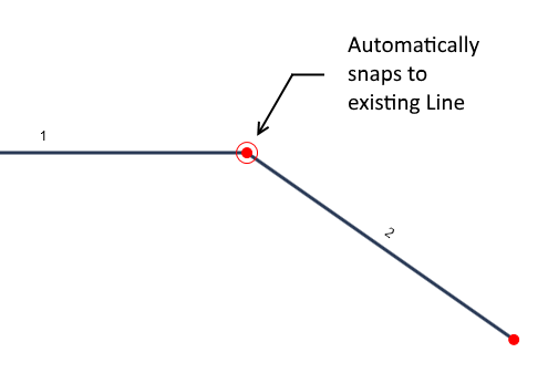
Connecting to a Downstream Line
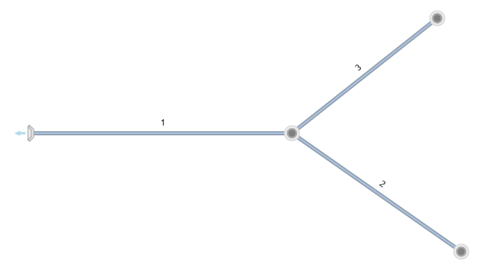
You can continue adding more lines as needed by repeating the above process. Simply move your mouse cursor near the downstream connecting junction and begin to drag. The program will automatically snap the two Lines together when you are within about 5 feet or 1 meter. A red circle appears around the connecting junction. If you are outside of this range, a new outfall Line will be created.
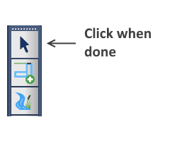
When finished adding all Lines, press the [Esc] key or right-click your mouse, or click the [Ok/Select] button on the side tool bar.
Again, you can always manually edit the Line’s length and angle afterward to get more precise. Also, the default junction type is a Manhole. It is assumed you will later modify the junction to the desired type, such as an Inlet, at the data entry step.
Adding From the Input Grid
You can also add single lines by clicking on the [Add New Line] button at the bottom of the Input grid. This will automatically add a new Line and set it’s Downstream Line Number to either the last Line added or the currently selected Line.
This method is particularly useful when the system’s Line lengths and angles are already known and you can just enter the data directly.

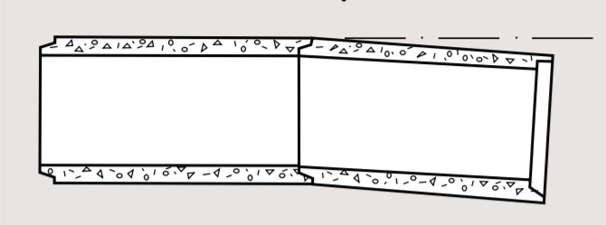
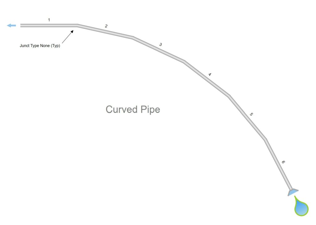
Curved Pipes
Changes in direction of sewer lines are usually accomplished at manhole structures, while grade and alignment changes in concrete pipe sewers can be incorporated into the Line through the use of deflected straight pipe. With that said, Stormwater Studio does not accept curved pipe segments, but you can enter a series of Lines with equal Lengths and Deflection Angles while using “None” as the Inlet Type.
The plan shown below required a total bend of 62.5 degrees between Line 1 and Line 6 with a total arc length of 288 feet. Each Line is 288/6 = 48 feet in length with a Deflection Angle of 62.5/(6-1) = +12.5 degrees.
Junction losses are computed at each bend but will be insignificant. For more details on junction losses please visit this page.
Maximum Deflection Angle
When installing deflected straight pipes, the joint of each pipe section is opened up on one side while the other side remains in the home position. The difference between the home and opened joint space is generally designated as the “pull”. The maximum allowable pull should be limited to an opening that provides satisfactory joint performance. This varies for different joint configurations and should obtained from the pipe manufacturer.
Using Radius Pipe as an Alternate
Radius pipe, also referred to as beveled or mitered pipe, incorporates the deflection angle into the pipe joint. The pipe is manufactured by shortening one side of the pipe. Because of the possibility of greater deflection angles per joint, sharper curvature with correspondingly shorter radii can be obtained with radius pipe than with deflected straight pipe. Check with local suppliers.