Stormwater Studio has an added feature that allows you to include a utility crossing entity in your model. This could include existing or proposed water mains, gas lines or any other type of underground structure. The purpose of this feature is to provide you with a visual model and a means to detect and anticipate possible elevation conflicts.
The software allows you to draw a single straight-line crossing anywhere on your Plan sheet. Please note that your project is only allowed one Crossing at a time. You can manually edit/specify the x, y coordinates at each end (labeled A & B) as well as a bottom elevation (z coordinate) at each end. Also included are height, width and shape. Shapes can be circular or rectangular.
Stormwater Studio takes care of the rest. It constantly monitors and calculates all possible intersection points in your model, as well as vertical clearances. If the Crossing conflicts with any existing Line, it will alert you on the plan. Crossings are automatically included in your Profile plots as well.
It should be noted that the software does not account for the wall thickness of the storm sewer line(s) when calculating clearances.
How to Add a Crossing
While on the Plan tab, click the [Add New Crossing] button on the side toolbar.
![]()
Next, move your mouse cursor over to the drawing canvas.
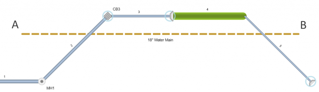
Position your mouse over Crossing end point (A). Drag (hold down the left mouse button and move) to draw the Crossing to the second end point (B). The Crossing coordinates are displayed on the input window to the right. Finish by releasing the mouse button.
Note: If you need to repeat, you’ll need to begin at the first end point (A) and drag to the second (B).
Lastly, to add this to your model, press the [Esc] key or click the [Ok/Select] button on the side tool bar.
Note that you can always manually edit the Crossing’s x, y points afterward to get more precise.
Crossing Data
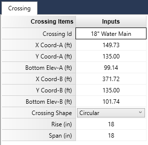
Once you have drawn your Crossing, the software automatically fills in the data input grid with the drawn coordinates. You may further edit those coordinates as needed as well as specify the elevations, shape and size of the Crossing.
To edit the Crossing, select it on the Plan view by simply clicking on the Crossing line. It will turn red in color and will label the end points as “A” & “B”.
Once selected, you can graphically modify the Crossing coordinates by hovering your mouse over the end points. A red snap-circle will appear giving you the ability to drag the point to a new location. Release the mouse to accept. There’s no need to click the [Ok/Select] button when editing.
Crossing data consists of the following:
Crossing ID
Optional. Enter any name or label that you wish to help identify this Crossing. For example, “12-in Gas Line”.
X Coordinate – (A & B)
After you have drawn your Crossing in, this data item is already set. Make changes as required.
Y Coordinate – (A & B)
After you have drawn your Crossing in, this data item is already set. Make changes as required.
Bottom Elevation – (A & B)
Specify the elevation of the bottom of the Crossing.
Shape
Choose the shape from the drop-down list box. It can be either circular (default) or rectangular.
Rise
Enter the overall height of the Crossing in inches or mm.
Span
Enter the overall width of the Crossing in inches or mm.
Note: Rise and Span must be equal when selecting circular Shape.
Conflicts & Clearances
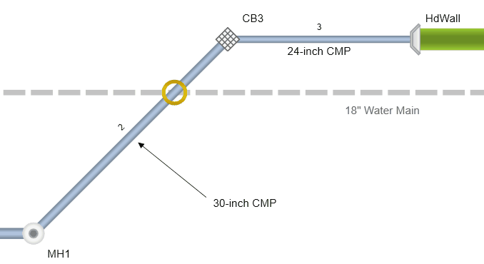
Once the Crossing is in place, Stormwater Studio will keep an eye out for intersections and conflicts. If it finds one it will place a yellow circle around its location as shown below.
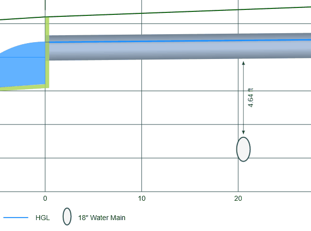
Your crossings will always appear on the Profile plots. If there’s enough room, a dimension label will be included to indicate the clearance. You may also hover over the Crossing to see the tool tip description indicating the clearance.