
Invariably you will need to modify the layout of your existing or newly drawn pipe system layout. Stormwater Studio offers a host of options for manipulating your system. The majority of your modifications need to be performed on the Plan tab but you may also edit any of the Line’s data items in the Data Input grid.
The most useful input for modifying your system is the Downstream Line Number located on the input grid under the Pipes tab.
How to Select Lines
Before making changes to your plan layout, or plotting multi-line profiles, you’ll typically need to select one or more Lines before doing so. Once you have selected a single or a set of Lines, you can perform edits on those Lines on either the Plan tab, Profile tab or on the Input grid.
To select a Line, click on the Line itself or its junction. The selected Line will turn red in color and the input window will populate with its data.
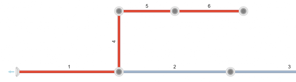
You may select multiple Lines by clicking on a Line or its junction while holding down the [shift key]. This method will select all Lines from the first selected Line, all the way downstream to the outfall. This is useful for performing edits on multiple lines or selecting Lines to view on the Profile tab. In the example below, Line 6 was clicked while holding the [Shift] key.
If you wish to only select, for example, Lines 2 and 5, select Line 2 and 5 while holding down the [Ctrl Key].
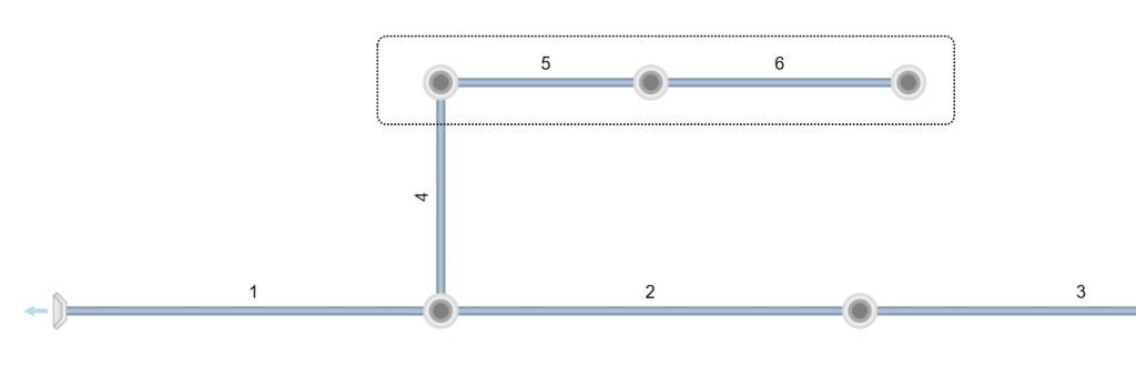
An alternate method of selecting lines is by dragging your mouse using the right mouse button. The program will draw a dotted rectangle around the selected lines. Any junction within the drawn rectangle will be selected. In the drawing below, Lines 4, 5 and 6 will be selected because their junctions are located inside of the rectangle.
Modifying a Line’s Alignment
You can graphically change the length and/or deflection angle of a Line by simply double-clicking on the pipe or its junction (at the upstream end). The Line will turn the color red indicating it’s been selected. Next, drag your mouse to the desired location and either click [Ok/Select] or press the [Esc] key to accept. Unlike adding lines, here you will have unlimited turns at positioning it.

Note that you may also edit any of the Line’s data items in the Data Input grid while in this editing mode.
Moving an Outfall
Anytime a Line has a zero Downstream Line Number, it is declared an Outfall Line. The procedure described above is used only to modify a Line’s length and deflection angle. If you wish to only move the downstream end of an outfall Line, position your mouse over the downstream end of the Line. The cursor will change. Then drag to the new location. Release the mouse button.
Moving a Branch of Lines
There will be occasions when you’ll want to relocate a Line or branch of Lines to an upstream, or even downstream, point. You can accomplish this task by editing Downstream Line Numbers. This can only be done by editing the value in the Input grid on the Pipes tab.
For example, in the layout shown below, the Downstream Line Number for Line 4 was changed from 1 to 2.
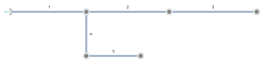
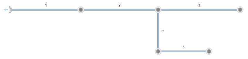
This was accomplished by selecting Line 4 and editing its Downstream Line Number to Line 2.
In cases where the new Downstream Line Number is higher than the Line(s) you wish to move, the software will automatically renumber your Lines in order to maintain the proper numbering sequence, i.e., Line Numbers must decrease in the downstream direction. Only the Line Numbers will change. Your data will remain intact.
Inserting Lines and Junctions
Stormwater Studio allows you to add a junction over an existing line, turning it into two separate Lines. The procedure is quite simple. Just select any existing Line and then click the [Insert] button on the side toolbar.
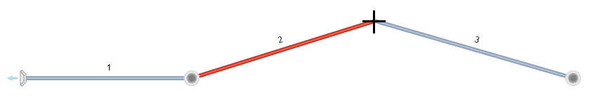
 For example, to insert a new junction somewhere on Line 2, select Line 2 (click on the Line or its junction) and click [Insert] on the side tool bar. A new junction will be placed at the center of the Line’s length. To adjust its location, double-click the line and edit as you would any other Line.


Note that the program will interpolate and assign invert and surface elevations to the new junction.
Deleting Lines
You can delete a single selected Line or a selection of many lines in your system. To delete, select the Line(s) to be deleted and click the [Delete] button on the side tool bar.
 The selected Line will be removed and the remaining Lines upstream will be renumbered.
You’ll be given a choice of either reconnecting the system back together or not.
Reconnecting the System
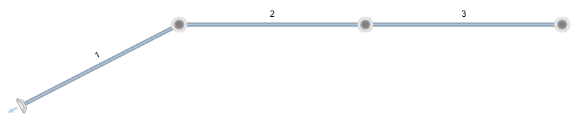
For example, to delete Line 2 below, select Line 2 and click [Delete]. Then choose ‘Yes’ to reconnect.

Not Reconnecting the System
The example above will look like this when not reconnecting. Note that Lock Junctions setting has no affect in this case.

Moving Multiple Lines at Once
You can move an entire system, from the outfall to its most upstream Line, by following these steps:

1. Unlock Junctions
2. Unlock Line Angles
3. Move your mouse cursor over the Outfall structure. Then drag to the new position.
Renumbering Your Pipe System
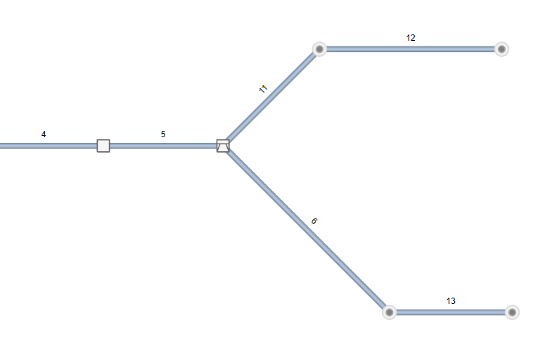
Its inevitable that after adding, removing, moving, etc. Lines in your system that it will become a hodge-podge of Line numbers. Even though it honors the numbering scheme the system could have numbers that jump around from one branch to another as shown below. Notice how Lines go from 13 to 6 to 5. Not logical.
You can renumber your system in a more logical manner by clicking the Renumber button on the side toolbar.

For example, the above system would then look like this:
 The new Line numbers are more orderly and thus makes it easier to do future edits.
Lock Junctions & Line Angles Options
On the top Ribbon menu you will notice two options in the Plan Layout category. Lock Junctions and Lock Line Angles.
These options allow you to freeze the junction positions and/or the Deflection Angles of the upstream Lines while editing a Line.
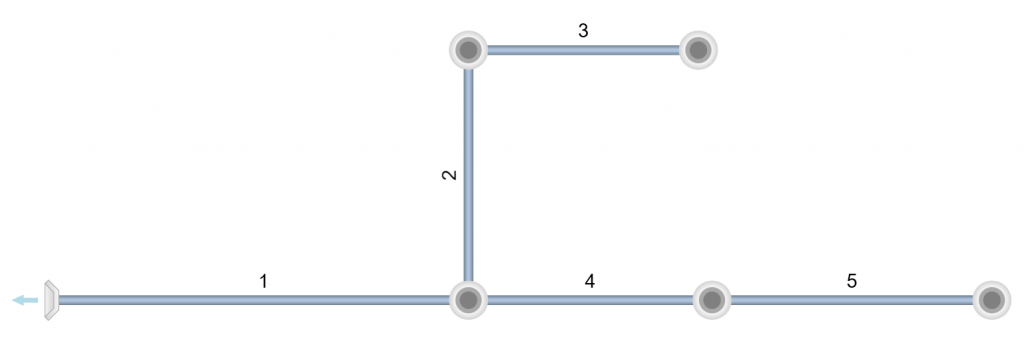
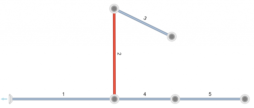
Lock Junctions
In the system below, Line 2’s length is edited (increased) with the option, Lock Junctions checked ON and then with it OFF. Notice how the junction of Line 3 remained in its original location with Lock Junctions ON but moved along with the edit when turned OFF.
Lock Line Angles
Sometimes you’ll have a need to move a junction upstream or downstream without moving the line itself. This is easily accomplished by locking the Line Angles. When locked, only the junction will move but nothing else.
Large Mouse Cursor
The last option in this category allows you to change the default cursor to a large cursor that spans the entire plan canvas. This is useful for aligning your Lines to other drawing entities. This cursor setting is automatically saved in the program’s Settings.
Note that using the large cursor may slow performance while working with large TIN surfaces that are visible. It is thus recommended to use the standard smaller cursor.