
In general, when building your storm sewer model, any number of Lines may enter a junction but only one Line may exit thus creating a tree-like structure. However, Stormwater Studio has the added ability to model flow diversions. This is where a junction can have more than one line exiting, thereby splitting the flows into two as shown below.

Stormwater Studio manages the flow diversion hydraulics automatically. There’s no need for you to guess at the split proportions or come up with a rating curve.
The software employs a very sophisticated calculation procedure which provides an exact balance between the flows and the resulting hydraulic grade line.
Any total Rational method drainage areas and Cs (Sum CxA) entering the diversion are split in the same manner.
How to Add Diversions to Your Model
Flow diversions are simply Lines. They are easily added to your model by following the same procedure as you do when adding any other new Line to your model. In this case, you’ll draw in the upstream direction as usual but towards the junction of the proposed split. In the case above, Line 6 was drawn towards the existing Junction of Line 3.
 The software will draw an orange circle around the diverting junction letting you know that 1) it is a valid junction to divert, and 2) it will be used as a diversion when you release your mouse button.
 Once you see the orange circle, release your mouse button and the software will take care of the rest.
In the image above, Lines 3, 4 and 5 were previously added. Then a new line 6 was added, drawn in the upstream direction, terminating at or near the junction of Line 3. Now the flows exiting Line 4 will be hydraulically split between Lines 3 and Line 6.
Definitions
When creating a diversion, there will be a Main Diversion Line and a Secondary Line. The Line containing the original junction is the Main. The Line it diverts to is the Secondary. In the example above, Line 3 is the Main and Line 6 is the Secondary. The Main can have any type of junction except a Headwall or None. The Secondary line has no junction is always assigned None. It’s just a pipe.
Some Restrictions Apply
You’ll be amazed at how the software automatically manages the hydraulics of flow diversions. With this level of simplicity and elegance comes some restrictions.
1. You cannot divert flows upstream. Doing this will create an endless loop during the calculations. Don’t worry, the software will prevent you from doing this. If you don’t see an orange circle while attempting to connect, the junction is not a valid diversion target.
2. Only one diversion can be created per project. Sorry, but having several diversions will get very, very messy.
3. Secondary Lines cannot be used as a Downstream Line for any other line in the system. Secondary Lines cannot have any Runoff data. Secondary Lines always inherit from the Main Line.
4. Diversions must be added graphically on the Plan tab. They cannot be imported or added from the Input Grid.
5. You cannot use the Renumber feature while the model contains a diversion. This prevents the possibility of creating a looping system. In this situation, temporarily disconnect the Secondary Line by editing (dragging away from the Main Line) converting it into an non-diverted Line. Proceed with Renumbering. Then reconnect to the Main Line.
What You Can Do With Flow Diversions
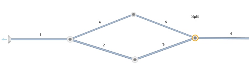
1. Re-introduce the diverted flows back into the system somewhere downstream. In the system below, flows arriving at the Split are separated and rejoined downstream at Line 1.
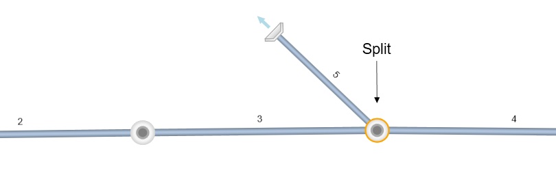
 2. Divert flows off-site or to another separate branch. In the plan below, flows from Line 4 are split. The flow that enters Line 5 is sent off-site.
How Flows Are Diverted
In theory, it is possible to determine the exact flow splits given the tailwater condition(s), physical and hydraulic properties of the outgoing pipes and the diversion structure itself.
And Stormwater Studio does just that…
Using an iterative calculation procedure, the software assumes flow proportions until the resulting HGLs from the Main and Secondary Lines in the diversion structure are matched within 0.075 ft (23 mm). No guesswork. No rating curves. These HGLs are shown in the HGL Report under the column heading, “HGLa”.
