
Stormwater Studio has the capability to simulate various storm sewer pipe systems, including open channels. It has the capacity to model up to 200 lines and inlets/junctions simultaneously. The software is equipped with advanced design features that are fully automated, allowing for efficient and accurate calculations. It can accurately compute a true, energy-based hydraulic grade line and perform a range of inlet calculations, such as gutter and inlet spreads and depths. Additionally, Stormwater Studio offers real-time interaction, providing users with a seamless and interactive experience.
Import entire systems from LandXML and DXF files is supported. Background Maps can be added from image files, DXF, or LandXML files that include Parcels, Alignments, or Plan Features. Moreover, TIN Surfaces can be imported to dynamically link with the system’s rim and ground profiles.
Once the system is input and computed, you’ll be able to produce multi-line profiles and several types of numerical reports that can satisfy most any deliverables requirements.
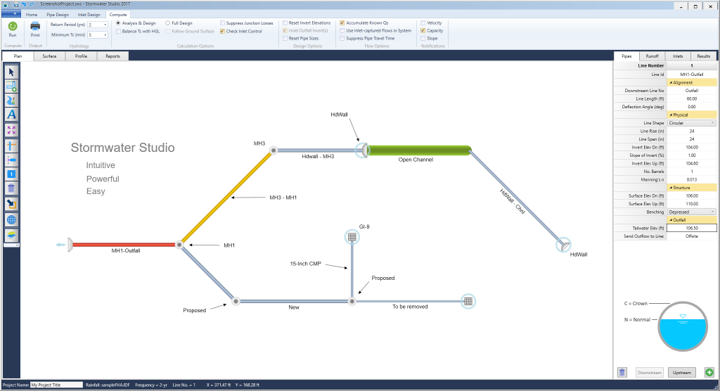
The user-interface was designed to minimize inputs, messy dialog boxes and put everything right in front of you. Below is the opening screen with an existing project Loaded.
In brief, Stormwater Studio was designed to allow you to develop a plan model of a storm sewer system consisting of Lines; adding data to these Lines; and computing a finished design. There are four basic steps in doing this:
- Drawing or importing Lines to your system
- Specifying associated data for each of your storm sewer lines
- Computing the results
- Printing reports and plotting profiles
It’s a very simple process that allows you to get comprehensive results in a short amount of time.
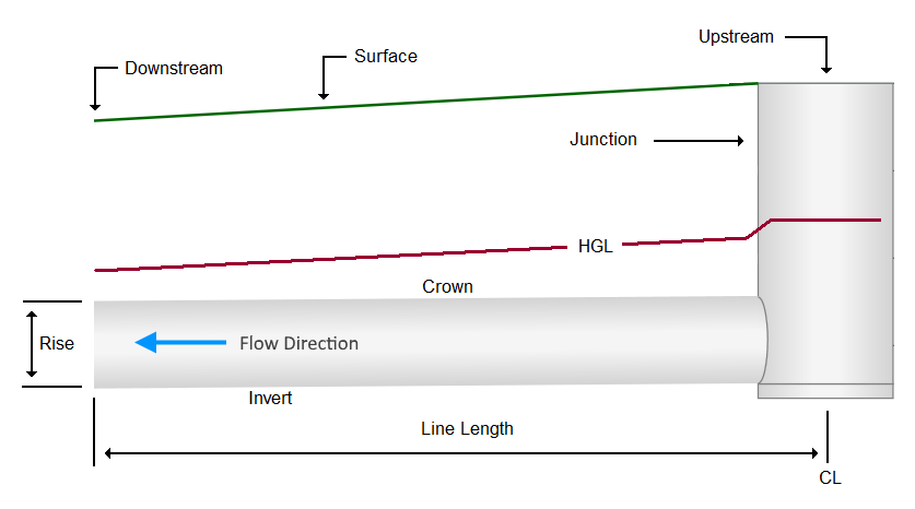
A Storm Sewer Line Defined
A “Line” is a length of pipe with a junction (manhole, inlet, headwall) at its upstream end. Lines are added to your model by drawing them starting at the most downstream end and working upstream. You can easily maintain a working model by only adding lines as necessary. There’s never a need to enter all of the anticipated lines initially. The program can handle up to 200 lines at once with multiple outfalls.
Lines can be made up of circular, rectangular, elliptical or arch pipes as well as open channels. Pipes can have multiple barrels.
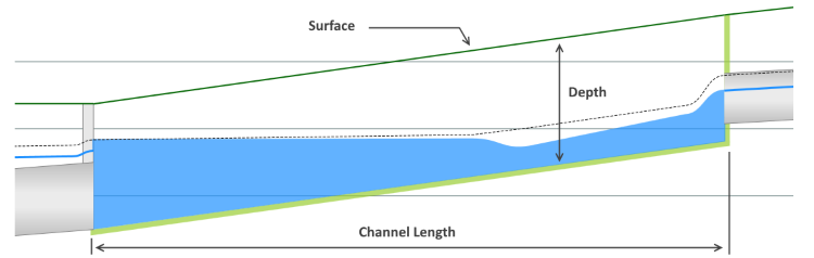
Below is a profile of a typical Open Channel. Open Channels are uniform in shape and can be trapezoidal rectangular, or v-shaped.
Plan Basics
Stormwater Studio automatically numbers your lines in the order that they are input. Therefore the first line that is input will be line number 1 and the second line input will be number 2 and so on. Typically, Line X flows into Line X minus 1. Part of the input data for each line will be the “Downstream Line Number”. This indicates to which line, Line X flows into.
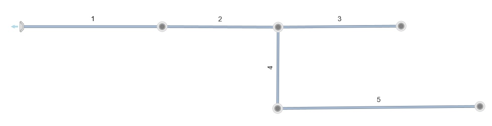
For example, in the system shown above, the Downstream Line Number for Line 3 is 2. The Downstream Line Number for Line 4 is also 2, i.e., Line 4 flows into Line 2. Similarly, Line 2 flows into Line 1, thus it’s Downstream Line Number is 1.
Note that a Line’s Downstream Line Number must be less than the Line Number itself, i.e., Line 2 cannot connect to Line 5. Line Numbers must increase as you work upstream.
Primary Working Tabs
You’ll see a set of tabs at the top of the main window, used for graphically manipulating, importing, exporting and viewing your model, as well as a set to the right. These tabs, Data Input tabs, are used for entering and editing associated numeric data. What’s important about these is that you can view and work on any combination of them at any time.
In the upper left are four tabs from which you’ll use to setup, manipulate and compute your storm sewer model.

Plan Tab
This tab is used to graphically draw and maintain your storm sewer model. It houses the canvas upon which you’ll build your model. Your project will typically begin on this tab.
It functions in a CAD like fashion in that it draws in real world coordinates. You can zoom in or out using your mouse wheel as well as pan by just dragging your mouse in any direction.
Surface Tab
This tab displays a close-up plan and section view of each inlet or junction in your model. It also draws a plan and profile of your Scour Protection Riprap Aprons. You’ll use this mainly to view the computed water surface and cross-sections of your inlets.
Profile Tab
The Profile tab displays a profile drawing of “selected” storm sewer lines. You can select lines from the Plan or Reports tab. It is on this tab tat you can interact with the software in real time to fine-tune your designs. Export profiles to DXF files and print them out in Letter or Tabloid-sized sheets.
Reports Tab
Displays a variety of pre-formatted and custom tabulated reports for viewing, exporting and printing.
Data Input Tabs
To the right you’ll find a second set of tabs used primarily for inputting Line and Flow data. Any of these tabs can be viewed while working on the primary tabs described above.
This window is always displayed on the right side of your screen and contains a spreadsheet-like grid for entering data associated with the lines drawn on the Plan. Once your layout is done, you can enter the associated data for each line. The Data Input window consists of three data tabs, each corresponding to a certain category. A fourth tab displays a limited amount of computed results.
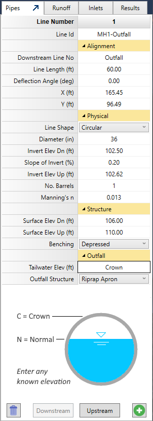
Pipes
Used to view and enter Alignment, Physical, Ground Surface and Tailwater.
Runoff
Used to specify the flow data (Drainage area, Inlet Time, Runoff Coefficients, etc.) for a particular Line.
Inlets
Use to enter data for the Line’s Inlet or Junction.
Results
Displays intermediate results for viewing while working on the Primary tabs.
The Data Input window is blank until you select a Line. To select a Line, click on the Line itself or its junction on the Plan Tab or a row on the Reports Tab. The input window will populate with its data. You may also select a line by clicking the [Downstream] or [Upstream] buttons at the bottom of this Data Input window.
Data can be entered on any tab in any order you wish. It behaves very much like an Excel Spreadsheet. To edit a cell, simply double-click or press [F2]. Type in your data item and press [Enter] or [Tab] to advance to the next cell.
Adding a Project Name
While optional, you may specify a name for your new project at the lower left corner of the main window in the Status Bar as shown below. This name will be included in all of your printed reports.