How Does Bioretention Work?
Bioretention, actually bio-detention, areas (also referred to as bioretention filters, bio swales, infiltration basins, or rain gardens) are structural stormwater controls that capture and temporarily store a pre-determined water quality volume (WQv) using soils and vegetation in shallow basins or landscaped areas to remove pollutants from stormwater runoff. They typically have a maximum contributing drainage area of about 5 acres. Highly impervious drainage areas should be 2 acres or less. Rain gardens are usually limited to residential lots, commercial parking and smaller areas.
Setting Up Your Pond For Bioretention
To effectively design a bioretention pond in Hydrology Studio, it is recommended to construct a single pond featuring two outlet devices: an exfiltration system and an overflow weir. This approach is straightforward. The Basin Model will look like this:

Utilize either Contours or Trapezoid shapes for defining the bioretention pond’s storage. It is important to note that the engineered soil layer, which consists of bioretention soil and gravel bed, should be excluded from the storage definition.
Do Not Include Infiltration Soil in Your Pond Storage
The reason is that inflow from runoff exits the pond through the bottom soil layer via infiltration, rather than through structural devices like weirs or orifices. This infiltration, also known as exfiltration, functions as a control outflow mechanism, similar to other outflow devices such as culverts.
Always remember that the Infiltration (a.k.a. Exfiltration) should be viewed as any other outlet device in the detention pond.
The bioretention soil layers themselves serve as the outflow device and are technically positioned downstream. Including the volume of their voids contradicts the principles of the Storage Indication or Level Pool routing methods. With or without an underdrain, the Bottom of Pond as shown above and below, should be Stage zero.

Outlet Devices
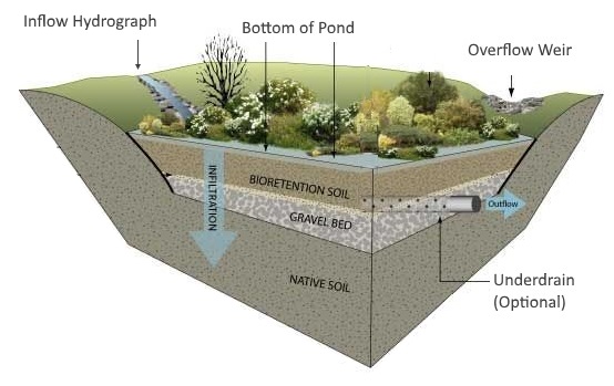
You’ll add the outlet devices in Step 3: Add Outlets when building your detention pond. The example bio-detention pond above shows to have two outlet devices:
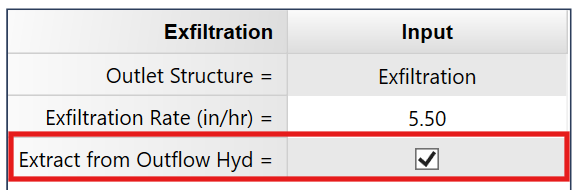
- Exfiltration (because it exits the pond) entered as a simple percolation rate typically in inches/hour per field tests. (A minimum percolation rate of 0.50 in/hr (13 mm/hr) is accepted by most jurisdictions.) This rate will be applied to the contour areas of the pond thus producing an outflow in cfs (cms) at each stage in the pond.
- An overflow weir. Typically a broad-crested weir. The size and crest elevation to be set to satisfy target outflow and drain-time requirements. Be sure to set the weir’s crest elevation below the top of the pond. Otherwise, the water surface in the pond will never exceed the crest. The WQv will need to be 100 percent contained below the weir crest elevation.

Underdrains
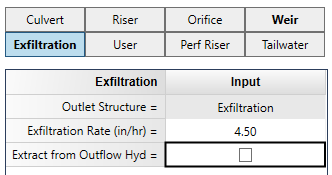
If the native soil beneath the bioretention layer cannot convey water at a minimum infiltration rate (usually about 0.5 inches/hr or 13 mm/hr), an underdrain should be included in your design. Underdrains re-introduce infiltrated water back into the outflow system. To account for this flow, uncheck the option, “Extract from Outflow” hydrograph as shown below.
Using a Bioretention Pond Forebay
Forebays are often used to capture a first-flush or water quality volume (WQv) before the runoff hydrograph reaches the main detention pond. There are two approaches you can use in the software:
Option 1. Remove the WQv from the inflow runoff hydrograph
When off-line structural controls such as bioretention areas and infiltration trenches capture and remove the water quality volume (WQv), downstream structural controls do not have to account for this volume during design. That is, the WQv may be subtracted from the total volume that would otherwise need to be routed through the downstream structural controls.
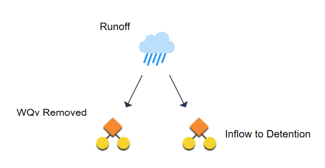
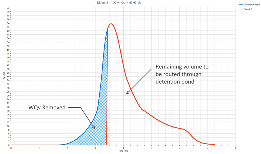
From a calculation standpoint this would amount to simply removing the initial WQv from the beginning of the runoff hydrograph – thus creating a “notch” in the runoff hydrograph. This can be accomplished by Diverting the inflow hydrograph using the “First Flush Volume” option. For more information, see, Diverting Hydrographs.
Option 2. Setup two ponds (forebay and detention)
The second option includes setting up two ponds, one for the Forebay or Bioretention pond, and the second for a more permanent pool Detention Pond as shown below.
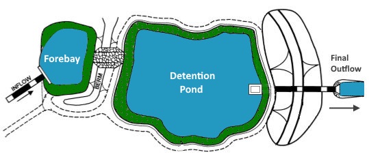
This is a multi-purpose infiltration-detention system. The Bioretention Forebay would be sized just large enough to contain the WQv and would have Exfiltration as an outflow device as well as an overflow Weir which would divert excess runoff into the lower, traditional detention pond.
Setting Up the Basin Model for Bioretention
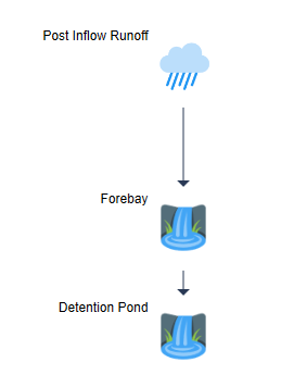
The most upstream inflow hydrograph would be routed through the Bioretention Forebay, creating an outflow hydrograph. That outflow hydrograph would then be used as the Inflow hydrograph into the second (Detention) pond. A second routing would produce the Final Outflow hydrograph.
Your Basin Model will look like the following where your runoff hydrograph is used as the Inflow into the first pond (Forebay). That routing will produce a hydrograph that will be used as the Inflow into the second pond (Detention Pond). Thus two pond routings.
When using a Forebay be sure to “Extract” the exfiltration when setting up the Forebay pond unless an underdrain is used and daylights into the second pond. You do not want the exfiltration to be included into the “inflow” to the downstream pond.
Drain Time, WQv and Extended Detention
To learn more about modeling for Water Quality Volume (WQv), Channel Protection Volume (CPv) and Drain Time, read these articles regarding Full Spectrum Detention and Volumetric Detention Pond Design.
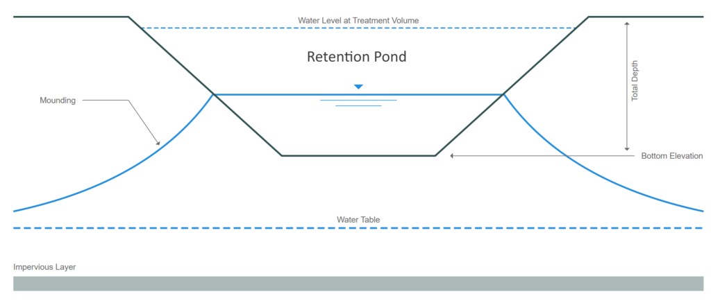
Retention Pond Recovery in Shallow Aquifers
Looking to calculate the recovery times (unsaturated and saturated) for retention ponds in shallow sandy aquifers? Check out Studio Express Groundwater feature.