This storage type assumes you will be creating a pond that is rectangular in shape, has a known bottom area, has equal side slopes (h:1) on all 4 sides and a desired maximum depth.
This pond shape can also be used for underground chambers that are box-type modules or vaults. It allows you to specify a void percentage to account for a reduction in volume due to interior supports, sidewalls, etc.
It automatically computes the stage storage table based on the following input items.
 To start, select the Trapezoid button. Then double-click the Bottom Elevation input on the input window.

Required Data
The following is a description of each of the required input items. Click the Help option button at the top of the input table to view a help diagram.
Bottom Elevation
Type in the elevation of the bottom of the pond.
Bottom Length
Enter the bottom length.
Bottom Width
Enter the bottom width.
Side Slope
Enter the side slope as a ratio. Example: For a 3 to 1 (horizontal to vertical) side slope, enter 3.
Total Depth
Enter the total depth of the pond. This number should include any freeboard.
Voids (%)
This value defaults to 100 and is useful for modeling gravel-filled trench drains. It allows for a reduction in storage due to gravel fills and such, but still allows the total surface area available for exfiltration calculations.
Click [Apply] when finished.
A completed output table based on the above inputs will look similar to the following:

Note that you cannot edit the Trapezoid output table. You must edit the values in the input grid.
Using the Interactive Tool
This will sure become your most favorite and productive way to fine tune your ponds. This tool contains buttons as shown below and basically allows you to edit most of the input items without having to re-type their values. Your edits will be applied automatically so you don’t have to click the [Apply] button each time. You’ll see instant results on your output table and associated graphs and plots.
![]()
Here’s how it works: Put your cursor on any input item, for example, Bottom Length. Then click on either the Arrow Up or Arrow Down buttons. This will increase or decrease the Bottom Length by 0.01 ft (0.001 m). The default increment is typically 0.01 ft. Holding the [Shift] key down increases the increment to 0.1 ft. Holding the [Ctrl] key down makes the increment 1 ft. Certain inputs are not adjustable using the Interactive Tool. For example, Voids. In these cases, the Interactive tool will show to be disabled or will beep.
Plan & Profile Charts
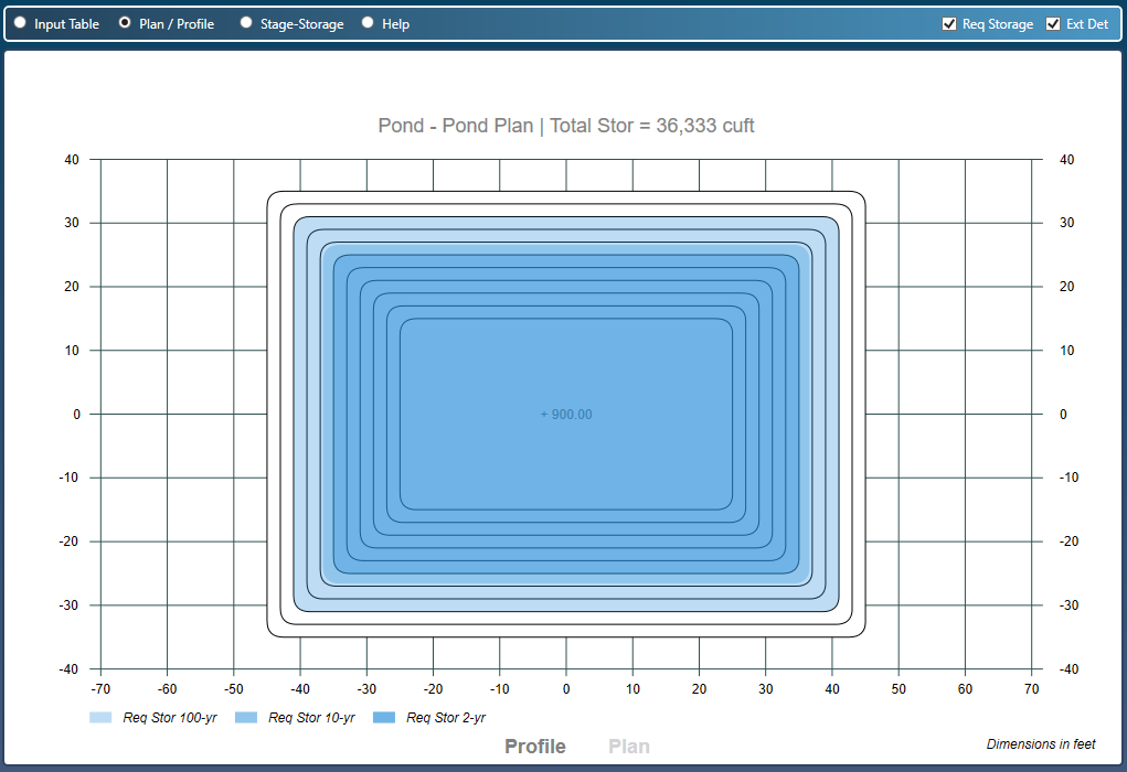
Once you have entered the data for the pond you’ll have the option to view your pond in plan and profile as well as a stage vs. storage chart. The plot below shows a Plan view along with the estimated storages as an overlay. Select the Plan / Profile radio button to view. Click the Profile text link at the bottom to view the profile.
Note that the Plan & Profile drawings are only available for Contours and Trapezoid shapes, not UG Chambers or Manual.
Stage-Storage Chart
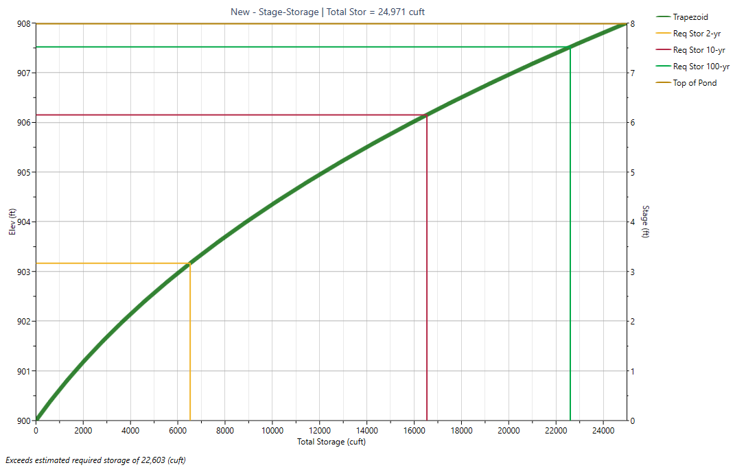
You can quickly view a chart of the Stage-Storage by clicking the Stage-Storage radio button. Notice in the chart below how the estimated required storages from Step 1 are plotted. The lines provide you with the corresponding elevations at each return period. For example, the estimated storage for the 100-yr event requires that it fill the pond up to elevation 907.5.
Now click the [Next] button to proceed to Step 3 – Outlets.