The following describes the data requirements for Pipes and Open Channels.
Pipes Data
Alignment
Line ID
Optional. Enter any name or label that you wish to help identify this line. For example, MHx – MHy.
Downstream Line No.
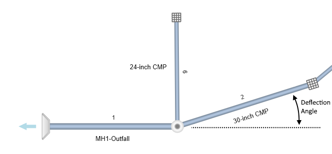
If you have drawn your system in, this data item is already set. If not, enter the line number which this line flows into. The plan below shows the Downstream Line Numbers of 2 and 6 is Line 1. The downstream line must have been previously input. The Downstream Line Number of Line 1 is always 0… Outfall.
Downstream Line Numbers must be < the upstream Line Number. For example, Line 10 cannot have a Downstream Line No. of 11. It must be 9 or less.
This software supports multiple systems (outfalls). Any line with a zero Downstream Line Number will become an Outfall.
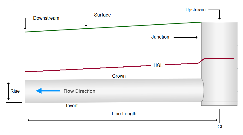
Line Length
If you have drawn your system in on the canvas, this data item is already set. Also, when adding lines from the Data Input window, the program initially sets its length at a default 50 feet (15 meters) and in the same direction as it’s downstream line. It is then intended for you to edit it as needed. Enter the length of this line in feet. It is the distance between junction centers.
Deflection Angle (Degrees)
If you have drawn your system in on the canvas, this data item is already set. As looking upstream, enter the angle between this line and the projection of its downstream line in degrees. Angles to the right are positive and angles to the left are negative. The deflection angle for Line 1 is usually 0. However, to change the orientation of your system, you can specify an angle for Line 1 or any other outfall line. Line 6 in the above plan has a Deflection Angle of -90 degrees.
X, Y Coordinates
If you have drawn your system in on the canvas, these data items are already set. You can directly enter or modify these values as you see fit. Once modified, the upstream end of this Line will relocate to the new X, Y position. The Length and Deflection Angle will change accordingly. X, Y Coordinates for the downstream ends of Outfall Lines can be edited also.
Physical
Line Shape
Stormwater Studio can model circular, rectangular, elliptical and arch pipes as well as open channels. Choose which type from the drop-down list box. Note that Stormwater Studio does not design pipe sizes for elliptical or arch sections.
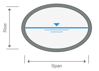
Elliptical Pipes
The program assumes elliptical pipes to be horizontal. You can enter any size for elliptical pipes, however the software will use ASTM Standard sizes when invoked, that is, if you enter a Rise corresponding to one of the standard sizes, the software will automatically insert the corresponding Span.
See Useful Tables for a list of the standard sizes and equivalent circular sizes. If zero is entered for the Span, the program attempts to insert a standard elliptical Span.
Arch Pipes
See Useful Tables for a list of the standard sizes. Enter any combination of Rise and Span. The arch pipe is treated as a half-elliptical when computing cross-sectional areas.
Line Rise or Diameter
Enter the diameter of the pipe or the height of the rectangular, elliptical or arch pipe in inches. To have the program size the pipe (circular) for you, enter zero.
If zero was entered for any one of the invert elevations, the program will size a circular pipe based on the Minimum Velocity. Otherwise it will design it based on Manning’s equation, setting the slope of the energy grade line equal to the slope of the invert.
Line Span
Enter the width of the rectangular, elliptical or arch section. You may enter a zero for a rectangular shape to have the program design it for you. There are no design options for arch or elliptical sections.
Invert Elevation Down
Enter the invert elevation of the downstream end of this Line. If you want the program to set it for you, enter zero.
Note that when adding upstream Lines, Stormwater Studio will automatically place a default value equal to the upstream invert of the downstream Line. If Match Crowns has been checked on in the Ribbon menu Pipe Design tab, then it will suggest a value that matches the crowns. (Provided a Pipe Rise has been specified).
Slope of Invert (optional) (%)
Enter the slope of this Line in percent. This input item is optional. If entered, the software will compute the upstream invert and will use it as the default value for the upstream invert elevation. If you do not enter a slope, the program will compute it based on the invert elevations you enter.
Invert Elevation Up
Enter the elevation of the invert at the upstream end of this Line. Enter zero to have the program set it for you.
Note that this item will automatically be set to zero if the downstream invert is set to zero. The program cannot design downstream inverts when the upstream invert is fixed.
The order of the Invert Elevations can be switched from downstream to upstream to upstream to downstream. Learn more here.
No. Barrels
Enter the number of side-by-side barrels this pipe has. It must be between 1 and 8. Note that you do not need to adjust the Line Length for this.
Manning’s n-Value
Enter the roughness coefficient for this line. The program will assume the default value of that is set in the Ribbon menu Pipe Design tab.
See Useful Tables for other suggestions.
Structure
Surface Elevation Down (Outfall Lines Only)
Unless this is an Outfall Line and no TIN Surface is present, this item will be “Read-only” and skipped. Enter the finish or natural ground elevation at the downstream end of this Line. This item will be used for design when calculation option “Full Design” is chosen. Otherwise this entry is only cosmetic. If left blank, the program will draw a dotted line at the “Minimum Depth of Cover” specified on the Ribbon menu Pipe Design tab.
Surface Elevation Up
Enter the finish or natural ground elevation at the upstream end of this line. This item will be used for design when calculation option “Full Design” is chosen. Otherwise this entry is only cosmetic. If left blank, the program will draw a dotted line at the “Minimum Depth of Cover” specified on the Ribbon menu Pipe Design tab. This input will be filled in automatically and be in a Read-only state when a TIN Surface is present.
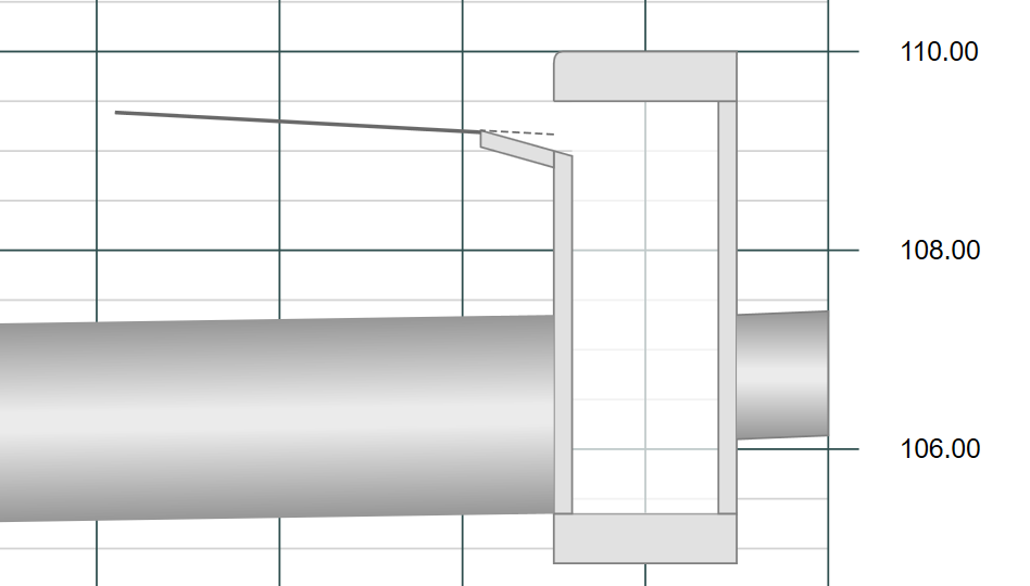
Surface Elevation for Inlets
The Surface Elevation for inlets correspond to the top-of-curb for Curb, Grate and Combination inlets; the invert for Drop Curb and Drop Grate inlets; and the Rim for Manholes. The Surface Elevation for the Curb Inlet below was entered as 110.00.
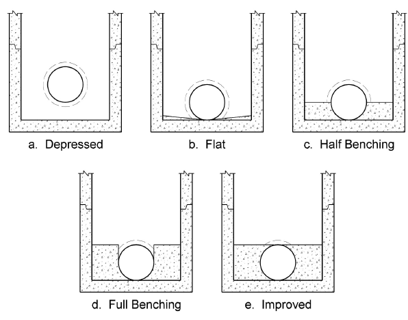
Benching
In addition to AASHTO, Stormwater Studio offers the calculation methods prescribed by HEC-22, Third Edition, as an option for junction loss calculations. Benching is one of the factors and needs to be chosen here. Select from the drop-down list box. The program will assume the default value of that set in the Ribbon menu Pipe Design tab.
Outfall (Outfall Lines Only)
Tailwater Elevation
Stormwater Studio will use this entry as the starting water surface elevation or beginning HGL when computing. This entry is only available for Outfall Lines.
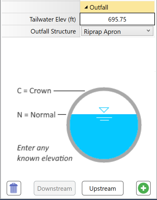
You have three options:
Known Elevation – Enter a known starting tailwater elevation.
(Subcritical flow profiles cannot begin below minimum specific energy.)
Crown – The is the default setting. This elevation will begin at the top of the pipe. To choose Crown, simply enter a blank value, zero, or the letter “c” or “crown” (no parentheses).
Normal – This will compute normal depth for the pipe and use it for the Tailwater Elevation. If normal depth is less than critical depth, then critical will be used instead. To choose Normal, type in the letter “n” or “normal” (no parentheses).
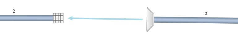
Send Outflow to Line:
This feature allows you to direct flows coming from upstream Outfalls to any other line in your system. For example, the plan shown below uses Line 2 to accept the flows exiting Line 3. To send flows off site, enter zero.
Outfall Structure
This specifies the type of structure at the downstream end of the Outfall Line, i.e., any Line that has a downstream Line Number equal to zero. (Not applicable to open channels). Select from the drop-down list box. Your choices are:
- Open Pipe (default)
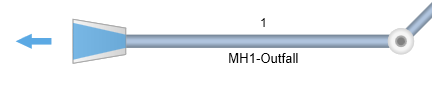
- Endwall
- Circular MH
- Junction Box
- Riprap Apron
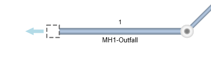
Note that this option will not affect the HGL calculations. Also, if you plan to move or change the position of the outfall, you must specify a structure other than an Open Pipe.
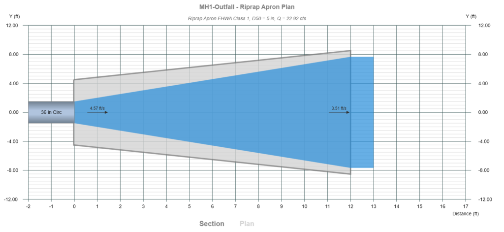
Riprap Aprons
When Riprap Apron has been selected for the outfall structure, the software automatically designs a riprap protection apron with no additional inputs.
These aprons do not dissipate significant energy except through increased roughness for a short distance. However, they do serve to spread the flow, thus reducing velocity, helping to transition to the natural drainage way or to sheet flow where no natural drainage way exists.
It employs the methods presented in HEC-14. It provides finished plan and profile views on the Surface Tab.
 Click the Plan link at the bottom of the drawing to view the Apron Plan.
Apron Design Numerical Outputs
These outputs are also available for inclusion into your Custom reports. For more detailed discussion on how aprons are designed, please see Computational Methods.
Length
The total required length of the apron.
Width
The width of the apron at the most downstream end. The Apron Width is computed using a 3:1 flare as shown in the example above. The width at the pipe outlet is drawn to: Pipe Span x No. Barrels + 2 x Span.
Depth
The required depth of the riprap. DO NOT take this design parameter lightly. The depth of your riprap is important but commonly gets neglected in the field. Eighteen inches is typically a minimum.
D50
The required apron rock size.
Velocity
The velocity of the flow at the downstream end of the apron. This is computed by assuming critical depth at the apron end. If the Tailwater is greater then the Tailwater is used as the depth. Then velocity is computed as Q/A where A = Depth x Width.
Class
Class of riprap developed by the FHWA Federal Lands Highway Division, 2003.
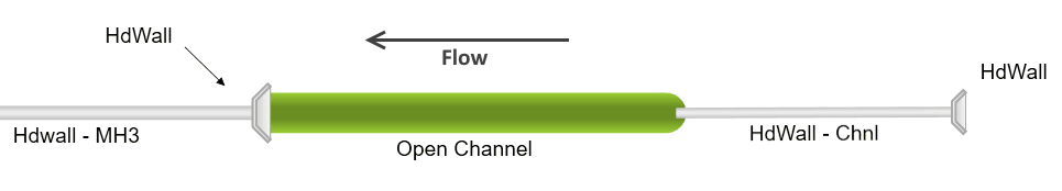
Open Channels Data
There are certain restrictions you’ll need to abide by when including Open Channels in your system:
- The Open Channel is just like any other Line in that it conveys flow in the System, not in the Gutter.
- The downstream receiving Line (if a Pipe) must have either a Headwall or None as its Inlet Type. Headwall recommended.
- There are no automated design options.
- The Surface Elevations are automatically entered as the Channel’s Invert Elevations plus the Channel Depth, so you will not need to enter them.
- Channels have no Inlet or Gutter and thus the Inlet type is set to “None”.
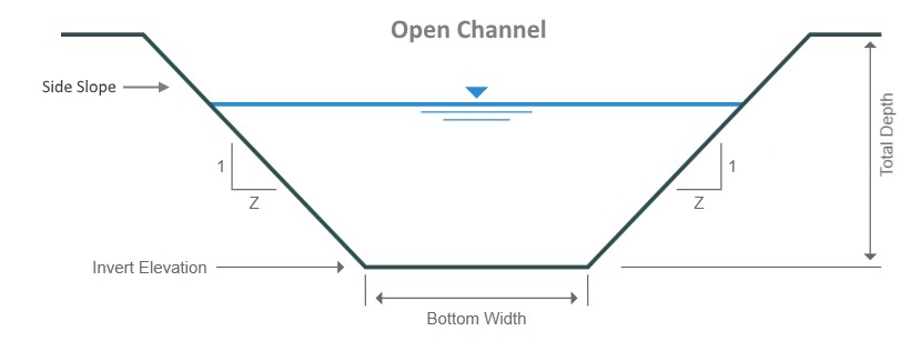
Open Channels are described by specifying the following:
Channel Depth
Enter the total depth of the channel in feet (m).
Bottom Width
Enter in feet (m). Enter zero for v-shaped sections.
Side Slopes
Enter the Side Slope, Z as (Z-horizontal to 1-vertical). The right and left side slopes are assumed to be equal. Enter zero for rectangular shape.