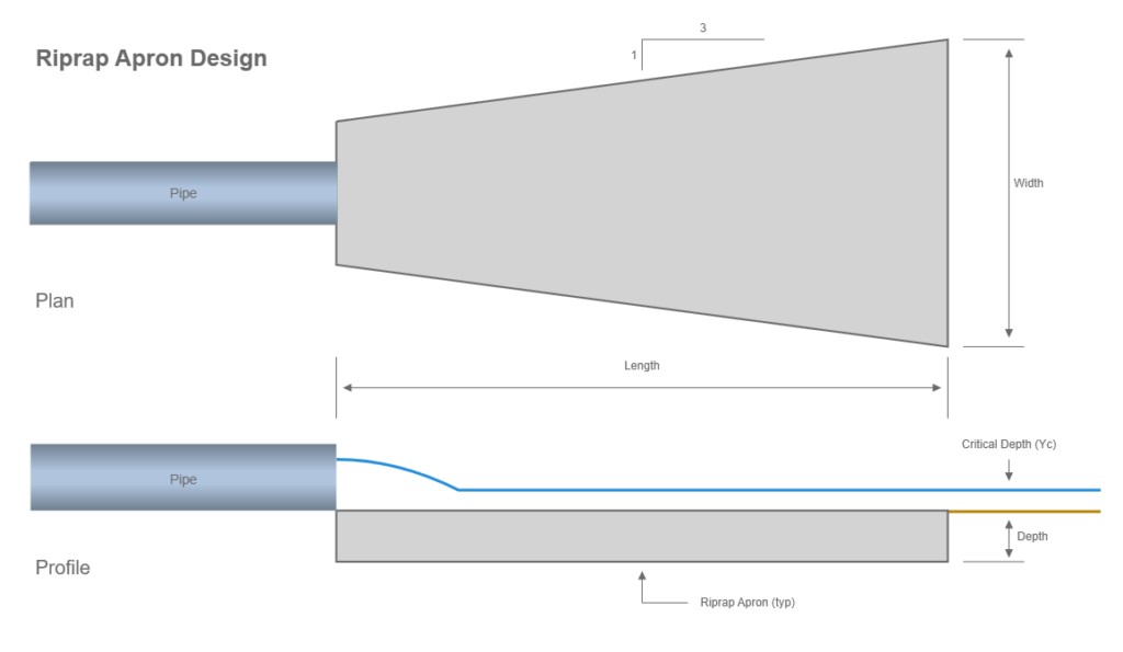
The most commonly used device for outlet protection is a riprap apron. An example schematic of an apron is shown below. The methods used here follow that of FHWA HEC-14, Third edition.

Riprap or grouted riprap is used to construct these aprons, which are positioned at a zero grade for a specific distance based on the pipe’s Diameter or Rise. Although these aprons do not dissipate a substantial amount of energy, they do increase roughness over a short distance. Their main purpose, however, is to distribute the flow, thereby reducing velocity and facilitating the transition to the natural drainage way or sheet flow in the absence of a natural drainage way.
The calculation procedure for determining the apron dimensions is relatively straightforward. First, the required size of the riprap rock, known as D50, is calculated. Then, the dimensions of the apron are obtained from a table.
The following equation is used to determine the Apron rock size, D50:

Where:
D50 = required riprap rock size in ft (m)
Q = discharge in cfs (cms)
D = Pipe rise (diameter) in ft (m)
Tw = tailwater depth in ft (m)
g = acceleration due to gravity
Tailwater depth is limited to between 0.4D and 1.0D. For example, if Tw is less than 0.4D then Tw = 0.4D.
Once D50 is determined, it is converted to whole inches (mm). The apron’s Length and Depth dimensions are then taken from the following table:
| Class | D50 (in) | D50 (mm) | Apron Length | Apron Depth |
|---|---|---|---|---|
| 1 | 5 | 125 | 4D | 3.5D50 |
| 2 | 6 | 150 | 4D | 3.3D50 |
| 3 | 10 | 250 | 5D | 2.4D50 |
| 4 | 14 | 350 | 6D | 2.2D50 |
| 5 | 20 | 500 | 7D | 2.0D50 |
| 6 | 22 | 550 | 8D | 2.0D50 |
The Apron Width is computed using a 3:1 flare as shown in the example schematic above. Once the final apron width is known, the downstream velocity is computed. This is computed by assuming critical depth at the apron end. If the Tailwater is greater, then the Tailwater is used as the depth. Then velocity is computed as Q/A where A = Depth x Width.
