Analyzing culverts from a hydraulic perspective can present significant challenges. A basic inquiry into culvert modeling often uncovers a plethora of four-letter acronyms and specialized jargon. In contrast, utilizing Culvert Studio for modeling provides a more tranquil experience. Thus, take a moment to relax and let the software handle the intricacies, allowing you to focus on achieving the desired results.
This application is designed to calculate hydraulic profiles and rating tables, encompassing a wide range of hydraulic characteristics for highway-type culverts. It employs advanced energy-based techniques to determine the hydraulic grade line (HGL).
The application is capable of managing both inlet and outlet control across various flow conditions, including partial depth, full depth, surcharged, roadway overtopping, and supercritical flow profiles featuring hydraulic jumps. The methodologies implemented are based on the guidelines outlined in HDS-5 (Hydraulic Design of Highway Culverts) and HEC-14 for assessing scour and designing automatic riprap aprons.
Modeling vs. Designing
The processes of designing and modeling culverts are closely interconnected, as there is no straightforward approach to achieving an effective design. This complexity arises from the influence of tailwater and the effects of inlet and outlet control. Relying solely on Manning’s equation will not yield accurate results for culvert performance.
An effective approach to culvert design involves inputting specific values and then conducting a modeling process. Start by determining an initial trial size, which can be selected either randomly or based on prior experience. Evaluate the outcomes to ensure they align with your design goals, which typically include factors such as velocity and headwater (Hw).
For instance, a slightly surcharged 24-inch culvert may prove to be a more cost-effective option compared to a partially flowing 30-inch culvert. Additionally, when height constraints are present, a rectangular design might be preferable over a circular one. It is also worth considering that two smaller barrels could potentially be more efficient than a single larger one, or vice versa. Ultimately, the best solution can only be determined by inputting various parameters and analyzing the results.
One of the standout features of Culvert Studio is its ability to rapidly model a diverse range of scenarios, helping you discover an optimal design that may not have been on your radar at the outset.
Let’s Get Modeling
The primary task in Culvert Studio is, of course, culverts. It is the default task selected upon launch.
Culvert Studio’s aim is to make simple work of sophisticated culvert modeling. It accomplishes this by combining a simple, modern user interface with rich, colorful graphics and detailed but friendly output.
Culvert Studio is capable of modeling culverts with various slopes, lengths, sizes, materials and shapes including circular, rectangular, arch, pipe arch, open-bottom arch, elliptical, circular – embedded and rectangular – open bottom. It also handles a multitude of culvert materials and inlet configurations.
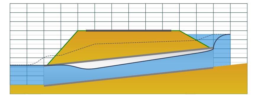
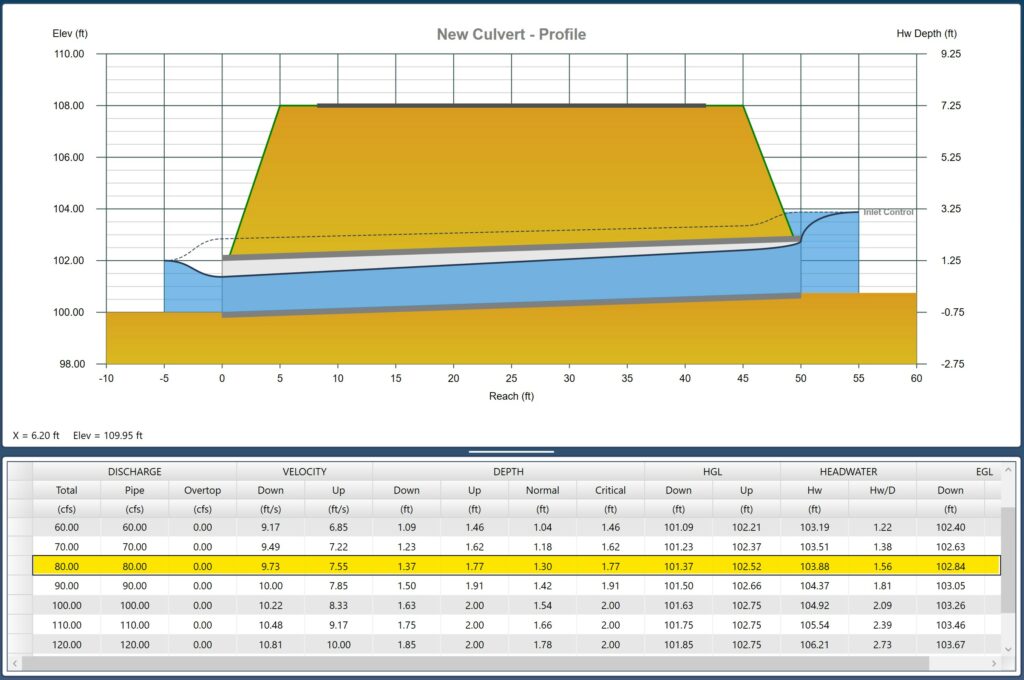
Culvert Studio is also a very sophisticated modeler in that it analyzes all flow regimes. Take a look at the profile below. The blue is the water surface and the dotted line is the energy grade line (EGL). That’s the water surface plus velocity head (V^2/2g).
When analyzing the flow from the downstream to the upstream direction, you will observe an increase in the Energy Grade Line (EGL) near the exit of the culvert, which signifies an exit loss. Following this, there is another noticeable rise in the EGL due to losses associated with a hydraulic jump. These losses tend to be relatively minor and stable as you progress towards the entrance, where a substantial entrance loss is encountered. Just upstream of the entrance, the velocity reaches zero, coinciding with the merging of the water surface and the EGL, resulting in a velocity head of zero. Approach velocities are not taken into account.
The various influences and outcomes make it more effective and efficient to create models rather than attempting to control all these variables in pursuit of a direct and flawless solution.
Modeling Broken-Back Culverts
Culvert Studio only models a single pipe run. If you need to model a culvert with two or more pipe runs at varying slopes, i.e., cases where the pipes need to duck under and temporarily travel beneath an obstruction such as a water line, and then slope back up to a normal cover, then you should use Culvert Studio’s sister program, Stormwater Studio. Please visit this article, “How to Model Broken-Back Culverts” for a complete description and example.
Basic Input Requirements
The input requirements are designed to be minimal but thorough. To enter data, type in the value or select from a drop-down input box, and press [Enter] or the [Tab] key. Following is a description of those required items. Once the data is input, results are computed by clicking the [Run] button at the bottom of the input grid. Then you can view the results. Please read Calculating Culvert Profiles for more information.
Data is divided into four categories:
- Culvert
- Embankment
- Discharge
- Tailwater
Following is a description of each. While entering data for the first time, the canvas will automatically display help diagrams to assist in your data entry.
Culvert Name
Optional but it is a recommended input.
CULVERT DATA
Shape
Select the barrel shape from the drop-down list box. This includes:
- Circular
- Rectangular
- Elliptical
- Arch
- Arch Pipe
- Arch Open Bottom (unique n-value for bottom from Project Settings)
- Rectangular Open Bottom (unique n-value for bottom from Project Settings)
- Circular Embedded (unique n-value for embedment from Project Settings)
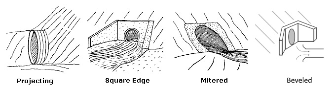
Inlet Configuration
Select an inlet edge from the drop-down list box.
Material
Select the barrel material from the drop-down list box. Note: The culvert’s roughness coefficient (Manning’s n) is based on this input. The corresponding n-values, including embedded/open bottom, used can be viewed/edited in Project Settings.
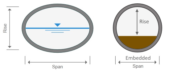
Rise
Enter the height of the barrel. Refer to image below.
For Circular – embedded pipes, this is the inside height between the crown and the embedment surface and must be greater than 1/2 the Span. In other words, the embedment depth cannot exceed 1/2 the pipe’s diameter. In which case you should use the Arch – Open Bottom shape.
Span
Enter the inside width of the barrel, all shapes. Circular, non-embedded sections, will always have equal Rise and Span.
Invert Elevation Down
Enter the invert elevation for the downstream end of the culvert.
Length
Enter the length of the barrel. The length for pipes with mitered inlets is measured along the shortest length (top or crown) of the pipe.
Invert Elevation Up
Enter the invert elevation for the upstream end of the culvert.
Number of Barrels
Enter the total number of barrels. Twenty is the maximum allowed.
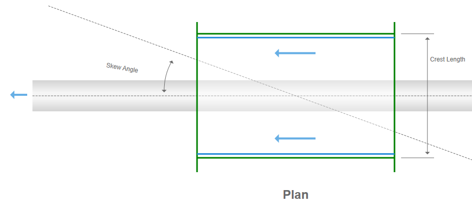
Skew Angle
Enter the skew angle in degrees as measured from a due west horizontal. Forty-five +/- degrees is the maximum.
How to Model Multiple Culverts With Distinct Properties
If you are modelling an existing culvert that was designed with multiple barrels, each featuring distinct sizes and invert elevations, please visit this article.
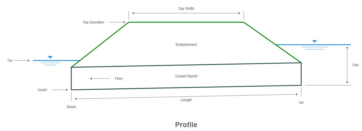
EMBANKMENT DATA
The embankment serves as the cover or roadway above the culvert. You can specify a constant Top Elevation and Crest Length or a set of user-defined station and elevation points (up to 25) for a roadway profile. The Top Width will be required in either case.
 Top Width
Enter the width of the top of embankment. This is assumed to be centered along the length of the culvert barrel. Must be less than Culvert Length.
Roadway Profile
Select from the drop-down list the type of profile you wish to employ. Constant Elevation or Varied.
Constant Elevation
This selection requires just two data items.
1. Top Elevation
Enter the elevation for the top of the embankment. This must be above the culvert’s crown. If your embankment roadway is super-elevated, enter the elevation of the highest side. The Top Elevation is where over topping occurs and serves as the weir crest elevation.
2. Crest Length
Enter the length of the embankment crest. Used as the weir crest length for over topping flow calculations.

Varied Profile
By choosing Varied, you may enter up to 25 Station, Elevation points to describe a roadway profile. Enter points as looking upstream, left to right. The first station will be zero.
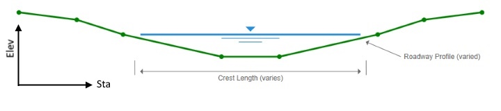
After selecting Varied from the drop-down list, click on the [Define…] button to open the Define Roadway window.
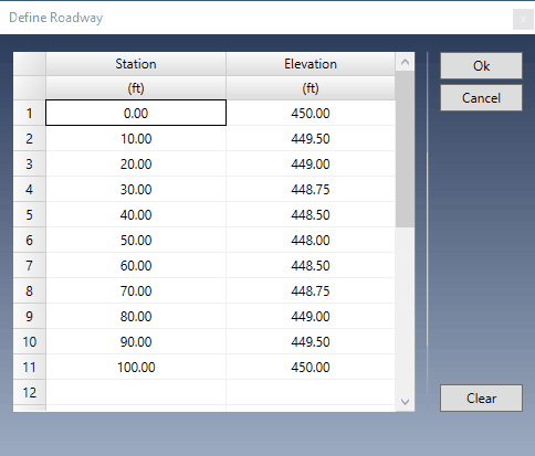
A user-defined profile is described by entering points containing offset stations and elevations as looking upstream. You must begin at Station zero. However, you may begin at any Station and the software will re-adjust all points, after clicking [Ok], to a zero starting point.
In addition, the software will “center” the finished profile over the Culvert Section. For example, using the sample data points above, the entire width of the profile is 100 ft. The software will plot the center of this profile at 50 ft, one-half of the total width. This is cosmetic only. The software is simply trying to consolidate the images. The results will be the same regardless.
Station
Enter the station for this point in feet (m) from the leftmost side. This is the distance from a baseline. Zero is suggested for Point No. 1.
Elevation
Enter the corresponding elevation for this point.
When done entering all points, click the [Ok] button.
Inserting and Deleting Rows
You can insert and delete rows by selecting a row and right-clicking.
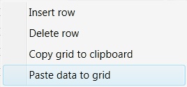
Copy and Paste Data
Similarly, you can copy the entire grid to the Windows Clipboard as well as paste previously copied data, for example, from a spreadsheet.
DISCHARGE DATA
Culvert Studio allows you to specify a range of flows as:
- User-defined flow increment (QMin/QMax)
- User-defined set of discharge values
- Rational method parameters
Discharge Method
Choose a method from the drop-down list. For modeling a single Q, choose Qmin, Qmax method.
Using Flow Increments
Q min
Enter the lowest discharge to be used for the calculations.
Q max
Enter the highest discharge to be used for the calculations. Set equal to Q min to model a single flow rate.
Q incr
Enter the incremental discharge to be used for the calculations. For example, if Q min = 50, Q max = 100 and Q incr = 5, the results will be computed from 50 to 100 in increments of 5, e.g. 55, 60, 65, 70, and so on. The program can process up to 100 unique discharge values. It will set a default for this input equal to 1/10th of the Qmax, Qmin difference but feel free to enter your own.
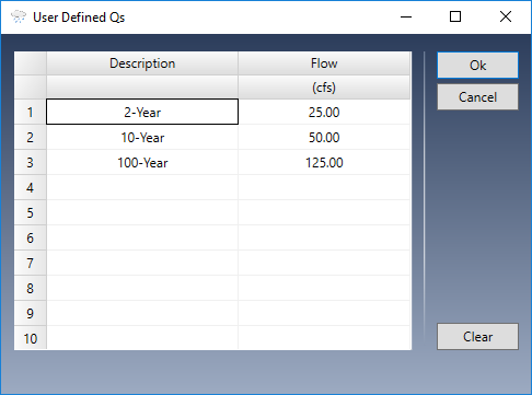
User-Defined Set
This method allows you to enter a custom set of ten unique Q’s. These may, for example, correspond to flows previously determined. Data can be copied and pasted by right-clicking on the table.
Rational Method
When using the Rational method, the program will automatically compute a set of discharge rates corresponding to the current IDF curves and using the following inputs:
Drainage Area
Enter the drainage area for this catchment.
Runoff Coefficient
Enter the Runoff Coefficient for this area. See Runoff Coefficients Table for suggestions.
Time of Concentration
Enter the time it takes for runoff to travel from the remotest point in the drainage area to the culvert opening in minutes.
TAILWATER DATA
When performing energy-based hydraulic grade line profiles, calculations must begin at the downstream end and progress upstream. This requires a known, or assumed starting water surface. Better known as Tailwater. Culvert Studio offers several options which you can choose from the drop-down list.
Normal Depth
Choose this to begin at a calculated Normal Depth (free outfall) for the particular discharge used. Normal depth is computed by Manning’s equation. Normal depth cannot exceed the pipe crown and may be less than Critical Depth when the resulting flow regime is supercritical.
Critical Depth
Choose this to begin at a calculated Critical Depth for the particular discharge used. Critical depth is computed by a variety of methods aiming to predict the depth at minimum specific energy. Critical depth cannot exceed the pipe crown. The resulting HGL may be below Critical Depth when the regime is supercritical.
(dc + D)/2
Choose this to start at (Critical depth + pipe diameter)/2. This is a conservative option. Use when the culvert is flowing full for most of its length.
Crown
Choose this to begin at the top of the culvert barrel.
Known Elevation
Choose this option to enter any known tailwater elevation. It must be above the invert of the culvert. Note that if this elevation is set below critical depth, critical depth will be used instead. Calculation procedures cannot succeed starting below minimum specific energy (critical depth).
Using a Channel Section
The options listed above are plenty adequate in most situations but Culvert Studio also allows you to specify an actual channel section which has been defined in the Channels task portion of the program.
Just select the channel you want to use from the Tailwater drop-down list and Culvert Studio will automatically compute depth, velocity, etc., for the channel and use it as the starting tailwater elevation. The discharge values from the Channel section do not need to coincide with those in the Culvert. The program will use the Culvert discharges instead.
If this starting HGL is below critical depth, then the starting HGL will be set to critical depth.
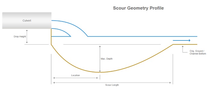
SCOUR DATA (optional)
Culvert Studio can estimate local scour at the outlet of your culvert. Scour is based on discharge, culvert shape, soil type, duration of flow, culvert slope, drop height (height above the natural bed) and tailwater depth. The software uses the computational procedures outlined in Hydraulic Engineering Circular 14 – “Energy Dissipators”. Culvert Studio assumes a fixed time duration of 30 minutes.
The inputs for scour are very minimal, in fact they are optional and can be disregarded if desired. In any case, the software will automatically compute dimensions for a protective riprap apron.
See Culvert Scour for more information.
Calculating the Culvert Profiles
Once you have input requirements met, click [Run] to generate the output. The Canvas and Results Grid are drawn and populated. The canvas plot will correspond to the selected row in the Results Grid. In other words, click on any row in the results grid to view its corresponding plot.
Click on any row in the results grid to view its corresponding plot.
The plot below shows the profile resulting from 80 cfs. (This 24-inch culvert is rectangular and has 3 barrels.)
Please see, Calculating Culvert Profiles for a complete discussion on the outputs.
Evaluating Your Results
Okay, you’ve entered the data and calculated profiles. Now what? Are the results good, bad, acceptable? Don’t worry about the flow regime, inlet or outlet control. Obviously it’s going to flow in one or the other. Check with your local drainage authority for specific design criteria, but these are two things you typically want to avoid:
- High Velocities. Check your velocities at both ends of the barrel. When they begin to exceed 6 ft/s (1.8 m/s) you’ll need to consider some form of erosion control at the outlet, such as a riprap apron. In addition, if you are designing for an embedded pipe barrel, you’ll need to consider erosion of the bedding material as well. If your culvert is flowing at a high velocity, it will wash away your embedment material very quickly. A high velocity is usually an engineering judgment based on locale and soil conditions, but as a general rule, anything over 12 fps is considered excessive.
- High Hw/D values. The headwater depth / barrel rise (diameter) should be kept below 1.5 and ideally 1.2 for larger barrels, those that exceed 30 sqft in cross-sectional area. If the Hw/D is less than 1.0, then consider using a smaller sized culvert. If the approach velocity in the upstream channel will cause scour, a short channel apron should be provided at the toe of the headwall. This apron should extend at least one pipe diameter upstream from the entrance, and the top of the
apron should not protrude above the normal streambed elevation.