Once the input requirements have been met, click [Run] to generate the output. If any erroneous data is present, the program will prompt you before proceeding. Otherwise, the Canvas and Results Grid are drawn and populated.
The canvas plot will correspond to the selected row in the Results Grid.
Canvas Drawings
The drawings are designed to be self explanatory. Rich colors, smooth Bezier curve technology make these charts friendly and readable. Select from the variety of radio option buttons on the top to view different chart types.

Profile

Section
Sections show the Crest Length and barrel section as looking upstream. The blue dotted line is the upstream Hw.

Plan
Culvert Studio automatically adds a roadway if the Top Width >= 12 feet. It adds a striped roadway when the Top Width >= 16 feet. It adds a centerline stripe when the Top Width >= 28 feet.

Rating Curve

Results Grid
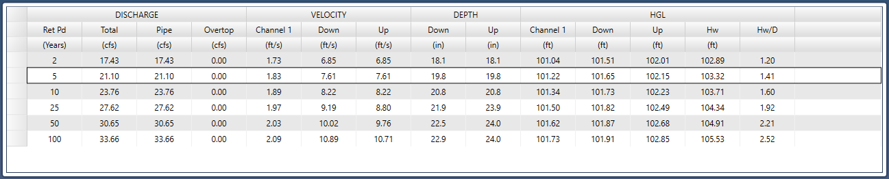
The Results Grid displays your output in a table that allows you to update your canvas drawing by selecting different rows.
Some columns are special to certain input requirements. For example, when using the Rational method, a column is added to show the Return Periods. Columns are also added to show the scour geometry and apron design when their respective plots are displayed. Please see Culvert Scour for more information.
Here’s a brief description of the columns and values:
DISCHARGE
Total
The total Q used for this computation.
Pipe
The Q conveyed by the pipe barrel only.
Overtop
Overtopping Q. This is flow over the embankment.
VELOCITY
Channel
This represents the velocity in the channel if one was used for Tailwater.
Velocity Dn
This is velocity of flow exiting the culvert. It is computed as Pipe Q / area of flow at the downstream end.
Velocity Up
The velocity of flow just inside of the upstream end of the culvert barrel. It is computed as Pipe Q / area of flow at the upstream end.
DEPTH
Depth Dn
The depth of flow at the downstream end of the pipe. HGL Dn minus Invert Elevation Down (or the embedment). Does not exceed pipe Rise.
Depth Up
The depth of flow at the upstream end of the pipe. HGL Up minus Invert Elevation Up (or the embedment). Does not exceed pipe Rise.
HGL
Channel
The hydraulic grade line at the channel section, if used.
HGL Dn
The hydraulic grade line at the downstream end of the pipe.
HGL Up
The hydraulic grade line at the upstream end of the pipe.
Hw
The headwater elevation. Includes entrance loss in outlet control.
Hw/D
Headwater to pipe diameter (or Rise) ratio.