Occasionally, you may encounter an unfortunate scenario where it is necessary to model an existing culvert that was designed with multiple barrels, each featuring distinct sizes, invert elevations, slopes, etc. The example culvert cross-section illustrated below displays two barrels: one with a diameter of 48 inches and the other with a diameter of 30 inches. The 30-inch barrel is positioned at a higher elevation compared to the 48-inch barrel, yet both maintain the same slope.

Your inquiry is: “What proportion of the total flow is directed through the 48-inch barrel, and what proportion flows through the 30-inch barrel?” Additionally, what is the corresponding Hw elevation?
Culvert Studio does not support the inclusion of multiple distinct barrel sizes within a single model. However, this article will guide you on how to effectively model such a scenario. The process is straightforward and involves modeling two separate culverts simultaneously.
Create Culvert 1 and Copy it to Culvert 2
For instance, you can create Culvert 1 and a copy of it as Culvert 2.
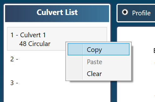
Right-click on Culvert 1 and select Copy.
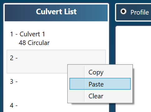
Right-click on Culvert 2 and select Paste. Now Culvert 1 & 2 are identical. Simply edit Culvert 2’s pipe data.
Both culverts will share the same embankment data, but each will feature different culvert properties. Specifically, Culvert 1 will accommodate the 48-inch barrel, while Culvert 2 will contain the 30-inch barrel.
It is clear that regardless of how the flow rate (Q) is distributed between the two pipes, the final Energy Grade Line (EGL) and Headwater Elevation (Hw) will remain consistent for both culverts. Our objective is to determine a flow combination that yields a reasonably identical upstream Hw. This can be achieved by modeling each culvert with various flow rates. By calculating and comparing the outcomes, we can pinpoint a shared Hw elevation at a target total Q.
There exists a particular set of flow rates that will result in a comparable Hw elevation.
The aggregate of these flow rates will indicate the total flow through the culvert section. An example is provided below.
Example Model of Two Distinct Culvert Barrels
Two culvert profiles below are shown as Culverts 1 & 2. Culvert 1 is a 48-inch and Culvert 2 is a 30-inch pipe. Both are 75 feet in length with similar n-values, inlet configurations, slopes, top width, top elevation, etc. The 30-inch sits 1-ft above the inverts of the 48-inch.
We aim to model a target flow rate of 231 cubic feet per second (cfs). Our objective is to determine the headwater (Hw) and analyze the distribution of flow between the two culverts.


It is recommended that you use a range of Qs for the Discharge Method.

The range of Qs set for Culvert 1 (48″) was Qmin = 100 cfs, Qmax = 200 cfs, Q increment = 1 cfs. And for Culvert 2 (30″), Qmin = 1 cfs, Qmax = 100 cfs, Q increment = 1 cfs.
The Tailwater Elevation (Tw) was set to “Crown” in both cases. We could have set the Tw to “Normal” or at a known elevation, say 105.00, the resulting common Hw would remain the same for both culverts.
Results are In
Once the results are computed, your goal is to find the pair of Qs whose sum total equals approximately 231 cfs while maintaining the same Hw Elevation (+/-). Below are their results and numerical grids.


After close observation, it can be seen that the common Hw is 109.02 ft. Culvert 1 conveyed 166 cfs while Culvert 2 conveyed 65 cfs. Note that each culvert flows at a similar velocty of 13.2 ft/s.
The table below presents the data in a more structured manner to effectively convey the message.
| Culvert 1 (cfs) | Culvert 2 (cfs) | Total Q (cfs) | Hw Culvert 1 (ft) | Hw Culvert 2 (ft) |
|---|---|---|---|---|
| 158 | 57 | 215 | 108.50 | 107.74 |
| 159 | 58 | 217 | 108.57 | 107.89 |
| 160 | 59 | 219 | 108.63 | 108.04 |
| 161 | 60 | 221 | 108.69 | 108.20 |
| 162 | 61 | 223 | 108.76 | 108.36 |
| 163 | 62 | 225 | 108.82 | 108.52 |
| 164 | 63 | 227 | 108.89 | 108.68 |
| 165 | 64 | 229 | 108.96 | 108.85 |
| 166 | 65 | 231 | 109.02 | 109.02 |
| 167 | 66 | 233 | 109.09 | 109.19 |
| 168 | 67 | 235 | 109.16 | 109.37 |
| 169 | 68 | 237 | 109.22 | 109.55 |
On the other hand, if you did not know the total Q or how it was proportioned, but had a target Hw elevation of say, 108.50. What would be the corresponding flows?
In the table above, in column “Hw Culvert 1”, locate Hw = 108.50. The corrsponding Q in that row = 158 cfs. Likewise, in column “Hw Culvert 2” find where Hw = 108.52. Its Q = 62 cfs. Their sum total is 158 + 62 = 220 cfs. A simpler alternative is to locate 108.5 Hw in Culvert Studio’s results grid for each Culvert and note their corresponding Qs.
This article aims to offer useful insights into modeling multiple culverts with diverse characteristics. It is important to recognize that there is no restriction to just two barrels or identical barrel shapes, slopes or inlet configurations. The objective is to identify the flow combinations that correspond to a common headwater elevation (Hw).