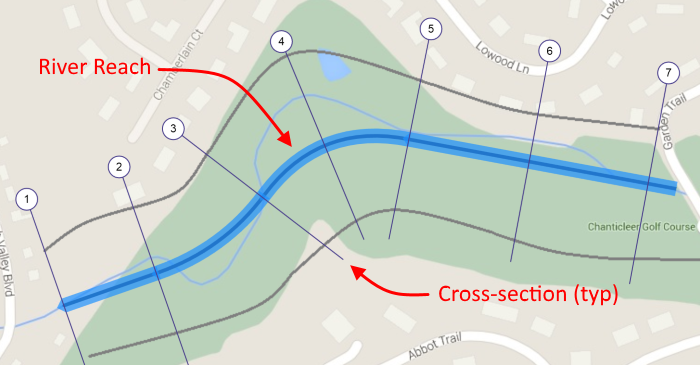
This is the first step in building your model… drawing in the river reaches. It is this reach, or collection of connected reaches, which will later hold your channel cross-sections. Your cross-sections will then contain geometry which describes the shape of the channel at each section.
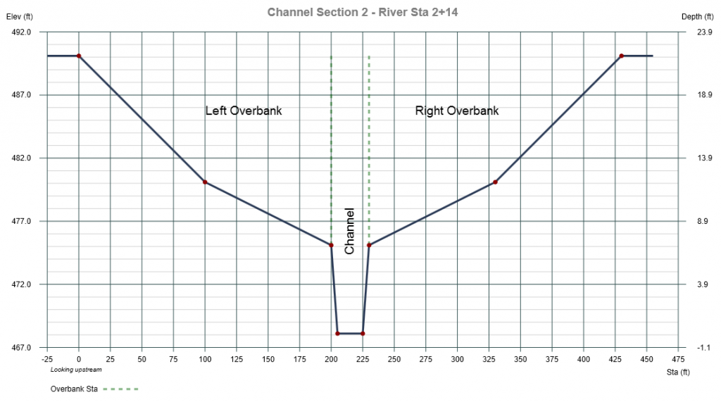
Your river stream will consist of one or more connected reaches which will ultimately contain cross-sections placed perpendicular along its centerline. These cross-sections will describe the actual channel and overbank geometry.
Your river reaches can consist of multiple interconnected segments, up to 100, and are X, Y coordinate based. A background map as an image, LandXML, DXF and/or TIN Surface can also be loaded to draw against if desired. The real-world coordinates of your mouse pointer are always displayed on the bottom left of your screen as well as the Reaches tab to the right.
Once drawn in, Reaches are fully editable by either changing the upstream Easting, X or Northing, Y coordinates manually or by double-clicking on the reach and then dragging the upstream end of the reach to its new position. It is not recommended to edit your Reach segments after adding cross-sections so spend some time getting this part right.
Setting the Drawing Canvas Scale
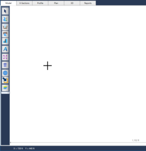
The drawing canvas opens up with preset X, Y (Easting, Northing) extents. The origin (Xmin, Ymin) is at the lower left corner of the canvas and is set to 100 ft., 100 ft. (10 m, 10 m). The Xmax extent is 1,100 ft. (510 m). The Ymax extent is computed based on your computer’s display aspect ratio.
X and Y dimension lines will be displayed on the Model tab indicating the absolute total distance in the X and Y directions. As indicated above, the default is 1,000 ft (510m) in the X direction. To increase or decrease these dimensions, simply roll (zoom in/out) your mouse wheel. This will help to ensure you have enough space to draw your proposed reaches. These dimension lines will not be shown when using coordinate-based background maps such as LandXML, TINs, DXF, etc.
Adding a Background Map
You can always model your system without the use of a background map. For example, if you already know that your total river reach is say, 1,000 feet and it contains ten cross-sections at various reach lengths, you can simply draw in a reach that is 1,000 feet long and then add your cross-sections where desired.
Coordinate-based maps such as LandXML, DXF or a TIN surface can optionally be used to draw against if you prefer an X, Y coordinate-based model. In these cases you will not need to adjust the drawing extents as they are baked-in to the map itself.
When utilizing non-georeferenced backgrounds, such as as bitmap images, you will need to set the canvas extents to match the map. Do this by clicking the map button on the side toolbar and selecting, “Set Background Extents” from the Map menu shown here:


See, “How to Add a Background Map” here for more detailed information.
How to Add Reaches
Reaches can be added to your model by two separate methods. You can either draw them directly on the model canvas or add them from the Reaches input tab.
1. Draw them directly on the Model
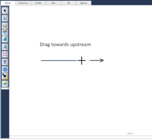
Channel reaches can be drawn by dragging your mouse, starting at the most downstream point of your model and moving upstream. Always draw your reach segments parallel to the direction of the “substantial” flow. When modeling an entire floodplain, the reaches should be parallel to the floodplain boundaries, not necessarily to a meandering “Channel” as shown in the above plan. The channel portion will be described in the cross-section data.
Each reach segment can be either curved or straight to match the actual channel or flood plain. The most downstream reach, Reach No. 1, must be straight.
Here’s how to do it Step-by-Step. Be sure to read Rules, Options & Tips below.
1. On the Model tab, zoom in or out with your mouse wheel to insure you have enough space to draw your reach. Then click on the River Reach button on the side tool bar.

2. Move your mouse pointer over to the drawing canvas and place it at the starting point, most downstream end of your channel system. It does not need to be at any specific X, Y point.
3. Drag your mouse to the upstream end of this reach and release the mouse button. The reach length and center-line station will be displayed on the status bar at the bottom left of your screen and on the Reaches Tab on the right while drawing.
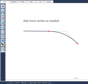
4. Repeat Step 3 for additional reaches until you’re finished drawing all of the them. Just start at the upstream end of the most upstream reach previously drawn. The program will display a red circle there and will automatically snap to it. Drag your mouse to the next upstream point. If you make a mistake, simply use the Undo button to go back one step.
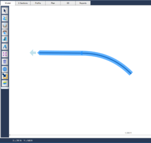
5. When finished, click the [Ok/Select] button on the top of the side tool bar or press the [Esc] key.

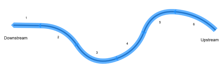
Below is an example of a typical river reach with six segments (five curved segments and one straight). The first segment must always be straight. All subsequent segments can be curved, or straight. You can force straight segments by holding down the [Shift] key while dragging.
2. Add them directly on the Reaches input tab
Rather than draw reach segments, you may optionally add them from the Reaches input tab.

Just click the [+ New] button and Channel Studio will instantly add a new reach segment to your model. If no reaches yet exist it will add one to the center of your model. If other reaches have already been added to your model, the new reach will be appended to the most upstream reach segment. By default, the new reach segment will be 100 ft (30.5 m) in length and will follow the bearing of the connecting downstream segment.
Once the reach has been added to your model, you can directly enter X, Y points of your choosing for the upstream end. Both upstream and downstream points can be specified for the beginning reach. Remember that Reach No. 1 must be a straight segment.
Click [Apply] to update the model. Channel Studio will automatically recalculate the reach’s Length, Station and drawing extents.
Adjusting the Width of the Reach Line
Use the Reach Width slider bar on the Ribbon Menu to change the drawing width of the reach. This is cosmetic only but is helpful setting the drawing canvas scale to match the map scale. Actual channel widths will be derived from your channel cross-section geometry.

Rules, Options & Tips
All reach segments are assumed to be curved, except Reach No. 1. By default, Channel Studio will plot it straight. No need to hold the [Shift] key.
- Reach No. 1 must contain at least one cross-section.
- Reach segments can be of any length. Use your mouse wheel to zoom in/out or contract/expand the canvas coordinates. Drag your mouse over the white space to Pan.
- Channel Studio will automatically draw curved segments. To insure smoothness, it uses the downstream reach as the Point of Curvature, PC, and the mouse position as the Point Tangent, PT. It will also draw dotted tangent lines, indicating the PI, for your reference while drawing.
- You can force straight-line segments by holding down the [Shift] key while dragging. If drawing Reach No. 1, holding down the shift key while dragging will force either a perfectly straight horizontal or vertical reach.
- Unless you’re aiming to produce coordinate-based, geo-referenced plan maps, a single straight reach can provide the fastest solution. Just draw a single straight reach making sure that your total reach length is long enough to contain your cross-sections. Curved or straight reaches, the actual channel and over bank reach lengths are what’s used to calculate the final water surface profiles.
- The program uses circular curve formulas for calculating reach segment lengths, and Bezier curves for drawing. Try to keep the deflection angle below 90 degrees. The dotted lines will turn red once this angle has exceeded 90 degrees.

Once you have your Reach drawn, it is a good idea to save your project so you can restore if needed.
Modeling a Curved Reach
If drawing against a map and you want to follow a defined channel or floodway, keep the leading dotted line (Leading Edge) within, and parallel to, the actual channel or floodway boundaries on the map to insure the next upstream reach will be on track and perfectly tangent. Use the leading dotted line as your guide. If it goes outside of the target track, just back up a little bit.


Modeling a Wide Floodplain
Modeling an entire floodway is easy. Just draw your reach along the center of the floodplain limits as shown below. Your cross-section data will pick up the actual channel and overbank locations.
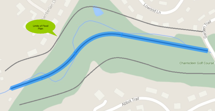
Your reaches do not need to follow the exact route of the “Channel” boundary. Remember, you can input reach lengths for the Left and Right Overbanks and Channel separately in the section geometry. The river reaches are just placeholders for your cross-sections.
For wide floodplains your reaches do not need to follow the exact route of the “Channel” boundary.
Channel Studio does not currently allow tributary river reaches. Only one contiguous river system. Tributaries can be modeled in separate projects. You can certainly add flows at any Section to include tributary flows.
You can add more reach segments at any time. Just snap on to the most upstream reach and draw as described above.
Editing Reaches
To edit an existing reach, you can either double-click on the reach itself and then drag the upstream end of the reach to its new position, or you can change the upstream Easting or Northing coordinates manually on the Reaches tab. Be sure to click [Apply] when done.

The upstream connecting reach, if one exists, will automatically adjust to maintain tangent lines.
Note that only the X, Y coordinates can be edited. River Stations and Lengths are calculated internally and cannot be edited directly.
Deleting Reaches
You may delete reach segments by selecting them with your mouse (click anywhere on the segment) and clicking the trash button on the side tool bar. Only the most upstream reach can be deleted.

Tip: Once you have your river reaches setup, it might be a good time to save your project file.