Channel Studio supports the addition of coordinate referenced background maps for display behind your Model and Plan views. This feature can be very useful when adding your river reaches and sections as it provides a coordinate-based alignment.
A variety of file formats are supported including, bmp, jpg, png, tiff as well as CAD-based DXF and LandXML files.
For image formats, you have the option of rectifying the picture by entering in two control-point coordinates. Ideally at the lower left and top right corners of your image-based map. But these points can be anywhere on the map. The further apart the better, however.
The program automatically assumes the extents implied in DXF and LandXML files, so control points are not required, or allowed.
How to Add a Background Map
Background maps must be added on the Model tab. Once added, the map will display on both Model and Plan tabs. It is recommended that you add background maps prior to adding your river reaches.
When importing image-type files, be sure the map is plenty large to work on. You can zoom in, but you cannot zoom out past the original image extents. If the image is too large, you’ll have the option of cropping it.
Once a map has been imported, you can zoom in or out with your mouse wheel as well as pan by dragging your mouse in any direction.
To add a map, click the Map button on the side toolbar from the Model tab.

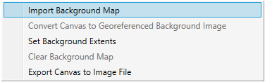
Then select, Import Background Map.
You can then choose your file from an open file dialog box. Note that you can select from .XML, DXF, BMP, JPG, PNG or TIF file types. Each of these are described below.
Importing LandXML Files
Channel Studio can import maps from any LandXML file containing Parcel, Alignment or Plan Feature elements. Once you have selected your file, the following screen is displayed:
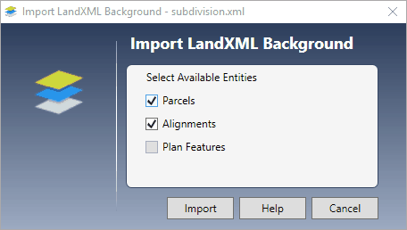
Select the entities available within the file and click [Import]. If the Entities checkboxes are disabled, then the LandXML file does not contain any Parcels, Alignments or Plan Features and cannot be imported.
Importing DXF Files
Channel Studio will import LINE, POLYLINE, LWPOLYLINE, ARCS and CIRCLES from any DXF file. Just select the file to be imported and click [Open]. It is recommended that you only import what you think you’ll need. Minimize the size of the DXF by selecting certain layers to export from your CAD software, and not the entire DXF file. Large DXF files can slow the Channel Studio down significantly.
Importing Image Files
Channel Studio will import from most image-based formats. Once opened, the map will display automatically. It will fill in the Model and Plan canvas’s uniformly until either the top is reached, or the sides, whichever comes first. The image will be centered on the canvas.
Georeferencing Your Image-based Map
Once imported, your map is just a set of un-georeferenced pixels, so it will be of little use. You’ll need to georeference it so that you can use real world coordinates to build your model.
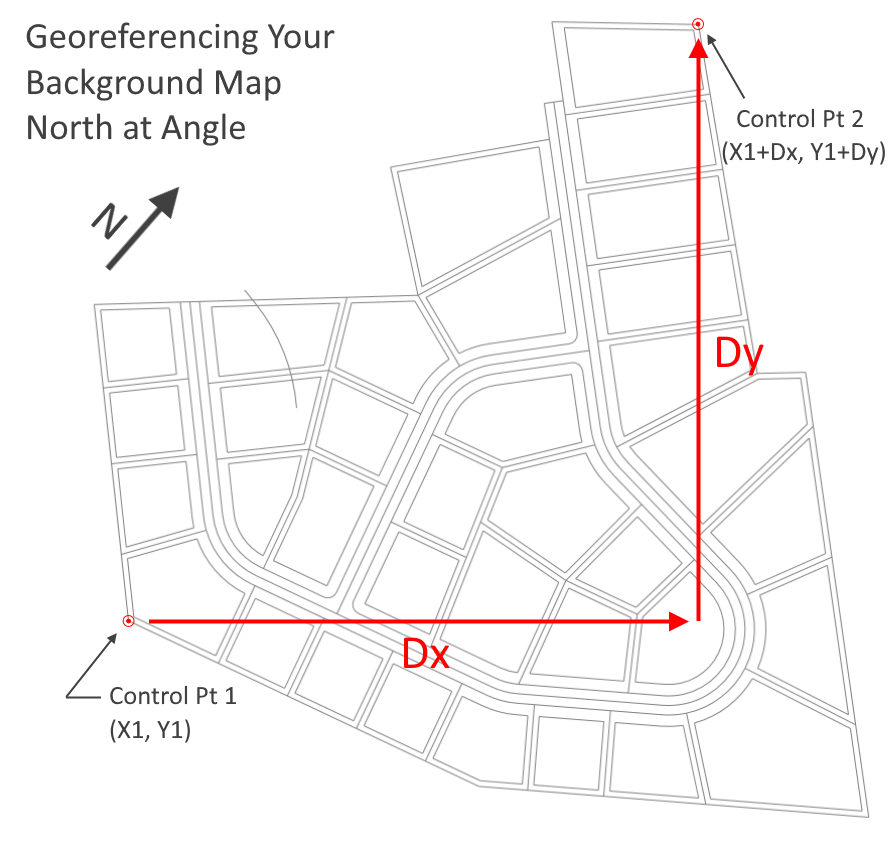
It should be noted that the software assumes North is straight up, not at an angle, when georeferencing. If North is not vertical then you’ll need to determine the horizontal distance (Dx) and vertical distance (Dy) between your two control points. If the angle of rotation is unknown, use of your plan’s graphic scale is recommended. See images below.
You can georeference your map by locating two control points on your map and providing their real world coordinates (X, Y) or Northings and Eastings, or scaled map-based coordinates. Prior to georeferencing, you will need to identify these two points on your map and obtain their real world coordinates. Once that is done, follow these steps:
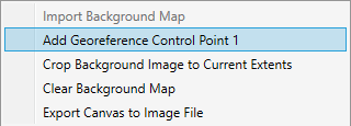
1. Add Georeference Control Point 1
Select “Add Georeference Control Point 1” from the Map menu.
Then place the cross-hair cursor over the control point on your map. (You can still zoom in/out and pan to better locate the exact spot.) Once there, click your mouse to select that spot. The Control Point window opens where you can enter the X, Y point as shown below:
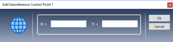
Enter the X and Y values and click [Ok]. The Control Point will be shown on your map for confirmation.
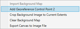
2. Add Georeference Control Point 2
Go back to the Map Menu and select “Add Georeference Control Point 2”.
Repeat the same steps as you did for Control Point 1 by moving the cursor to the point on your map and clicking your mouse. Then enter the corresponding coordinate point and click [Ok].
Your map is now georeferenced.
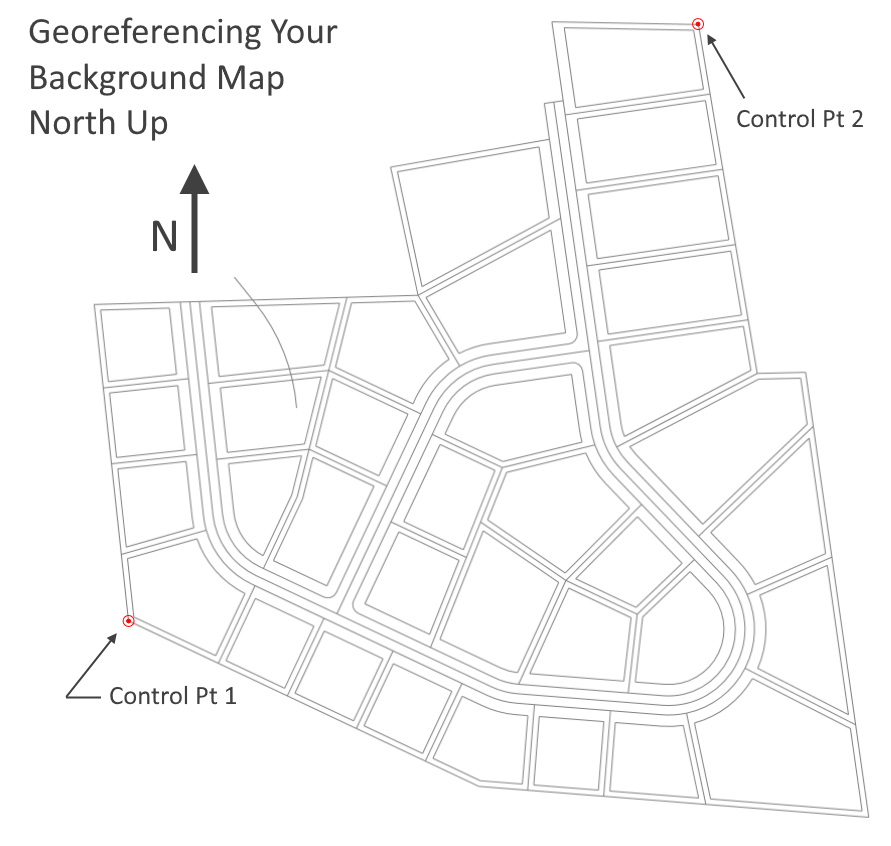
It is recommended that your control points be as far apart as possible (both X & Y) to maximize the georeferencing accuracy, similar to example shown above.
Note that georeferencing can only be done once. In other words, you cannot edit the control points once they have been set. If you made a mistake, you will need to clear the background map and start over.
Cropping Your Image-based Map
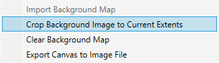
Sometimes your background images are too large for your specific project boundary. You can narrow the space by simply zooming in and panning (with your mouse) to manipulate the image to your desired zoom level and location. Once this is done, select “Crop Background Image to Current Extents” from the Map menu.
This will set the extents of the map to exactly what is shown on the canvas. Be sure to leave yourself ample room on the map as you can zoom in, but not out beyond the original cropped image.
It is recommended that you georeference your map prior to cropping in case your control points fall outside of the cropped image.
How to Add a Background Map Instructional Video
Be sure to watch this video on how to add a background map and georefrence it.
Using World Files
Channel Studio will recognize and automatically utilize a World file. A world file is a six-line ascii text sidecar file used by geographic information systems to georeference raster-type maps. It typically will share the same name as the image file but will have a “w” added to the file’s extension. The second character of the original extension will often be deleted in order to main the three-letter standard. For example, tfw or jgw.
While opening your specified image file, Channel Studio will see if an associated world file is present in the same folder as the image file. If true, it will use that data and insert the X, Y coordinate points for you when you add the two control points.
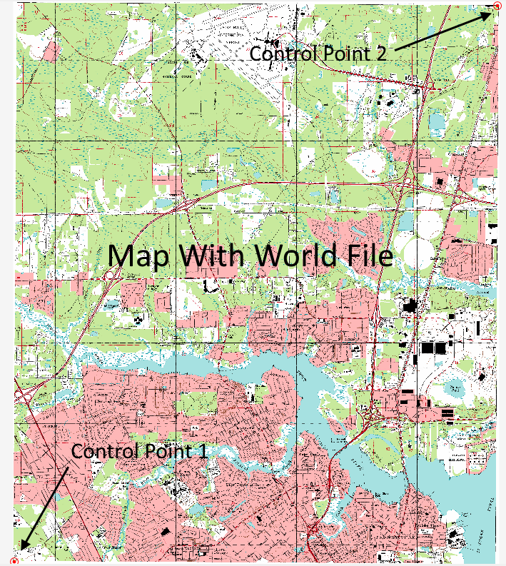
Georeferencing with a world file differs slightly from the procedure outlined above. You will still add two control points, but they must be placed as follows:
Control Point 1 – At the lower left corner of the map.
Control Point 2 – At the upper right corner of the map.
Once you have clicked on the designated corner, the Control Point window appears as usual but with the X, Y coordinates already entered. You just need to click [Ok] to accept. Perform this procedure for both control points.
You can override the world files points by just following the procedure for non-world file images. Locate your own control points and enter the corresponding X, Y values, overwriting the ones supplied by the world file.
Clearing the Background Map
You may unload the map from your display by selecting “Clear Background Map” from the Map menu shown above. There may be cases when you just needed a map to develop your channel model but not needing it afterwards. You can remove the map and your model will stay intact with the georeferencing.
You can add the map back again if you’d like but you may need to re-georeference it to align it back up with your model.
Setting the Background Extents
Even if you’re not using a background map, but a blank canvas instead, you can adjust the extents of the Model canvas to whatever you’d like. But it’s just as easy to simply scroll your mouse wheel to expand or contract the canvas’s existing coordinates.
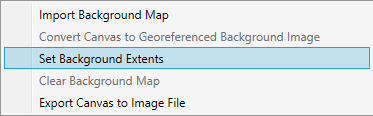
To adjust the canvas coordinates, select, “Set Background Extents” from the Map menu shown below.
You will then be prompted to set the map extents by the following screen:
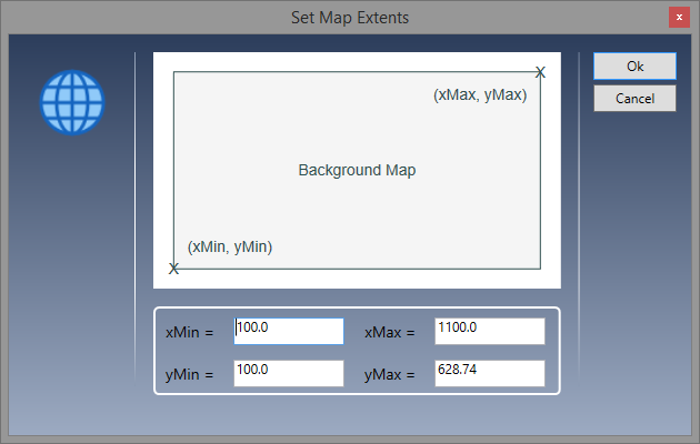
Enter the X, Y coordinates associated with the lower left and upper right corners of the map and click [Ok]. A default value for the upper right (yMax) value will be inserted for you and will be based on your screen size and aspect ratio.
Saving Background Maps
DXF-based Background Maps ARE NOT saved with project files but their file path locations are. When the project is reopened, Channel Studio will look in the file path location for the dxf file and reload it. If you plan to share your project with someone, be sure to provide them with the actual DXF map file.
LandXML maps, including TIN surfaces, ARE saved and will be embedded within the project file.
Image-based maps will be saved but as a separate side-kick file, apart from its original. It will be saved under the same name as the project file but with a .bmp extension. Like the dxf, Channel Studio will look for this file and reload it.