
Stormwater Studio has the ability to design and analyze a system of inlets along with your underground pipe system. It has built-in capability to analyze the following inlet types:
Curb
Grate
Combination
Drop Curb
Drop Grate
Headwall (Can include optional overtopping weir)
Generic (Known Capacity)
Manhole (Not really an inlet but is one of the junction types)
Inlets are located at the upstream end of a Line and can be in a sag or on a longitudinal slope and can be of any size.
The purpose of this analysis is to determine the amount of flow a particular inlet can capture, the ponding depth, inlet and gutter spread widths, the amount of flow that is bypassed, and what affect it has on downstream inlets.
The program also has features that will automatically size inlets to capture 100% of the flow. Basically, if an inlet Length, for example, is set to zero, the program will design it automatically.
Default Data
When adding a new inlet, the program automatically assigns default values for you in order to speed up the process. The default values are set on the Ribbon menu Inlet Design tab. Note that the Default values are applied to newly added inlets only. Changing the defaults will not affect any existing inlets you previously entered.
Clogging Factors
Unique Clogging factors can be specified for inlets containing a curb opening or a grate, on grade or in a sag. These can be set and adjusted on the top Ribbon menu Inlet Design tab. Clogging factors are global in that they will be applied to all inlets in the project.
Methodology
Stormwater Studio follows the methodology of FHWA HEC-22 for inlet interception capacity calculations. It uses FHWA HDS-5 methodology for computing losses at Headwalls (Check for Inlet Control must be ON in the Compute tab).
Flow Development
Stormwater Studio uses a separate procedure for determining Qs for inlets than that for the overall pipe network. The Qs for inlets are computed using the Rational formula, Q = CIA, just as it does for the pipe system. But the intensity is based on the individual catchment’s Inlet Time, not the cumulative Tc. Known Q’s are automatically added to overland flows.
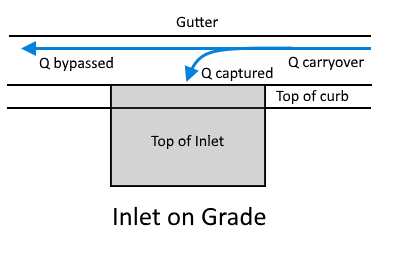
Carryover and Bypassed Q’s
Q’s for individual inlets are developed from two components. The first is from the catchment’s drainage area or runoff. The second component is from excess flows, or non-captured flows from upstream inlets. This non-captured flow is called “Carryover”. It is called “Bypassed” when an inlet cannot capture 100% and sends a portion of the total flow off site or to another specified target inlet.
Carryover and bypass flows are both non-captured flows. To an inlet, carryover is an incoming flow and bypassed is an outgoing flow. These flows are labeled as “Q carryover ” and “Q bypassed” on the reports. Note that Lines with a manhole, headwall with overtopping weir or no inlet, will bypass all carryover flows to its downstream Line.
Inlet & Gutter Spreads
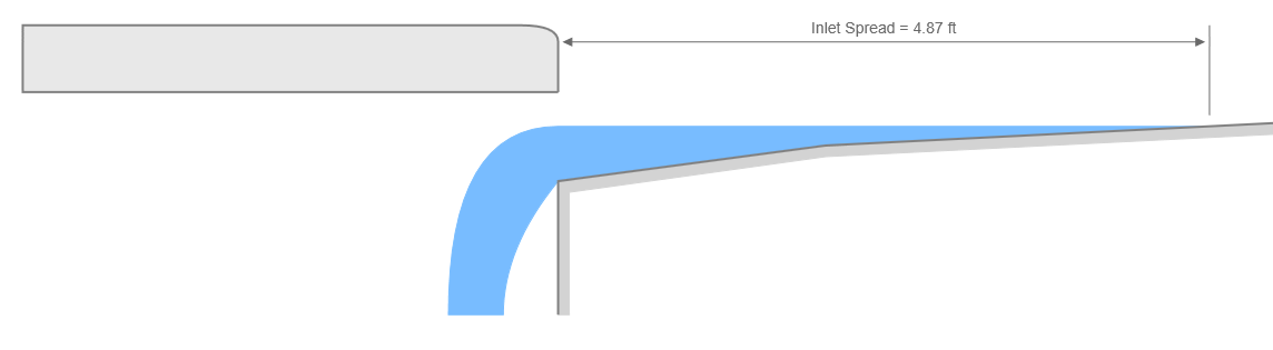
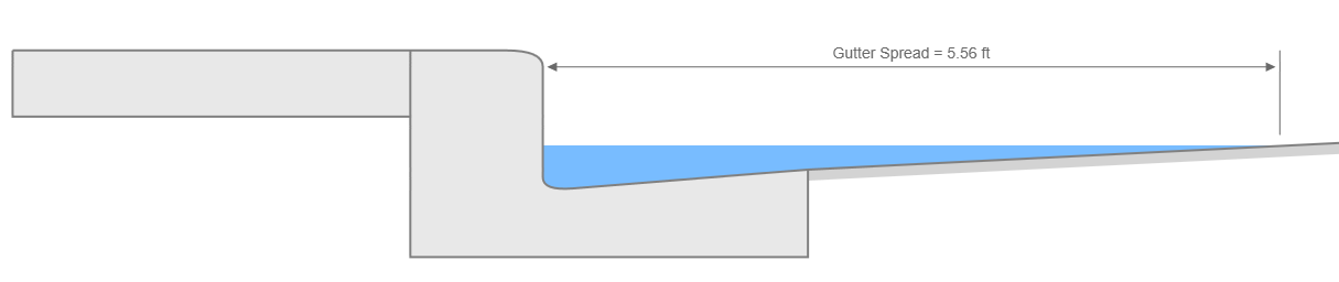
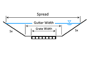
In short, spreads are reported at the face of the inlet and also just upstream of the inlet. When an inlet is in a Sag condition, the spreads are the same and are determined by the depth (water surface elevation) at the inlet face. This elevation is simply projected across the Sx and Sw cross-slopes to determine the spread.
When On Grade, as shown in the two cross-sections below, the two spreads can be different but keep in mind that spreads are typically higher upstream of the inlet face and the gutter properties, Sx, Sw and Longitudinal Slope influence the spread widths the most, not so much the inlet itself. The inlet is designed to capture flows and remove them from the gutter, but can do little to manage spread widths upstream.
See Inlet and Gutter Spreads in Computational Methods for more discussion.
When Gutter Spread Exceeds the Maximum
Inlet spread widths are typically based on the dictates of local regulations. If the maximum allowed spread width is exceeded, the design must be adjusted by relocating the inlet to a point upstream in the curb and gutter section which will reduce the drainage area, the peak discharge, and thus the spread width. Repeat this process until the spread width is at or below the allowable.
Common Inlet Data
Regardless of which type of inlet you use, they will each have four common data items.
Inlet Id (optional)
Enter any name or label that you wish to help identify this inlet. For example, G7.
Inlet Type
Choose the type of inlet from the drop-down list box. Each of these inlet types are described individually below in this article. A manhole is the default structure.
Location
Please choose this inlet’s location (On Grade or Sag) from the drop down list box. Note that inlets On Grade must specify the gutter’s longitudinal slope. If the inlet is in a Sag, then there will be no bypass flow. All of the flow will be captured. Inlets On Grade may or may not capture 100 percent of the flow.
Bypass Target
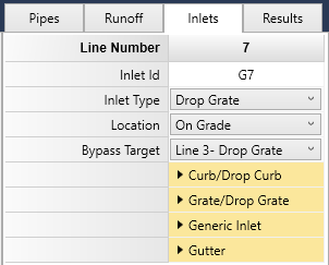
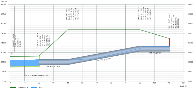
Bypass target Lines are those Lines that accept Bypass flows from inlets that are On Grade. In the system shown below, the Bypass Target for Line 7 is Line 3. Thus all flows which were not captured by G7 will flow to the inlet at Line 3, G3. By default Bypass Targets are the Line’s Downstream Line.
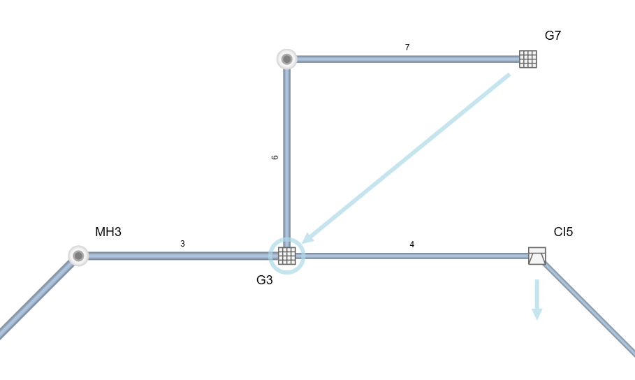
Enter the number of the Line to which bypass flows from this inlet are to go. Enter zero to have the flows sent off site. Note that unlike Downstream Line Numbers, inlet bypass flows can be sent to any inlet in your system, including upstream. This is most useful for when gutters flow opposite their Line flow.
This target will be indicated on the Plan view when “Gutter Lines” has been checked ON at the Ribbon menu Home tab.
Inlet Types
The remainder of this section provides descriptions of the required data for the types of inlets you can model.
MANHOLE

Although not actually an inlet, it is the default structure and it has no data requirements. It should be noted that Stormwater Studio will allow you to model an entire system using only Manholes. That is, any junction can be a Manhole while having a drainage area, runoff coefficient, Tc and/or known Q. Flows will enter the pipe system but there will be no inlet or gutter analysis associated with it. This may be an advantage when your inlet requirements have been met and you’re only interested in the pipe hydraulics.
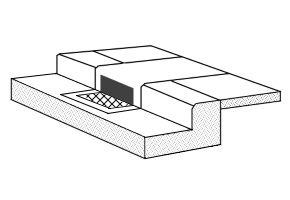
CURB INLET
Curb inlets are the workhorses of the industry. Pound-for-pound they are the most effective of all the street-type inlets and get a high rating for capture capacity. They are most effective in sags and when on grades of less than about 3%.
A typical curb opening inlet will have a rectangular opening along the face of the curb to which it is attached. Curb inlets can have Horizontal or 45-degree Inclined Throat openings. This data item is fixed for all inlets of this type in a given project and can be set in the Defaults on the Ribbon menu Inlet Design tab.


Inlet Length
Enter the total horizontal length of the opening. By setting this value to zero, Stormwater Studio will automatically design it for 100% capture.
Throat Height (Horizontal throat)
This is the height of the opening and is measured from the projection of cross slope, Sx. Do not include any local depression amount. See Gutters for more information.
Throat Height (Inclined throat)
This is the height of the opening and is measured perpendicular to the throat opening angle (assumed to be 45-deg). Do not include any local depression amount.
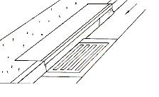
GRATE INLET
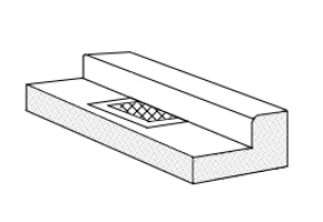

Grate inlets are deceiving in that they appear to be able to capture a lot of runoff because they are flush to the gutter. But in fact, they are the least effective among the street inlets.
When utilizing grate inlets, it is important to manage expectations regarding runoff removal, particularly when they are installed on grade. The challenge lies in the fact that their ability to capture runoff is heavily influenced by the upstream spread widths, which are generally much broader than the width of the grate. Consequently, most runoff that extends beyond the grate’s width will simply flow past it, preventing effective capture. Additionally, clogging presents a significant concern with these systems.
The objective in designing an effective grate inlet on-grade is to maintain the flow width within the gutter, ensuring it does not extend beyond the width of the grate. To enhance its efficiency, it is more beneficial to increase the width of the grate rather than its length.
Opening Area
Enter the clear opening area of the grate. Required only in sags.
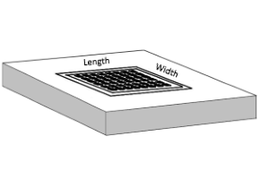
Grate Width & Length
Enter the width and length of the grate.
Set the Length to zero for automatic design. The program will size the inlet length for 100% capture. When Stormwater Studio designs for grates in sags, including combination inlets, it sizes the grate opening area using the “Grate Design Depth” in the Ribbon menu Inlet Design tab.
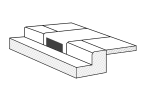
COMBINATION INLET
Combination inlets can capture up to 18% more flow than a stand-alone grate inlet, due to their ability to remove debris from the grate. Combination inlets require the same input data as both Curb and Grate Inlets. Combination inlets are assumed to have horizontal throat openings, no inclined throat.

Per HEC-22, the capacity of combination inlets on grade is equal to the grate alone and that the curb-opening is used to collect and remove debris. Capacity is computed by neglecting the curb opening.
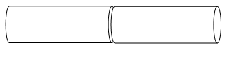
Combination “Sweeper” Inlets
Note that you may enter unique lengths for the grate and curb opening. When the curb opening length is longer than the grate length, the program assumes the open curb portion to be located upstream of the grate, often called a “sweeper” inlet.
The sweeper inlet has an interception capacity equal to the sum of the curb opening upstream of the grate plus the grate capacity. The grate capacity of sweeper inlets is reduced by the interception of the upstream cub opening.
DROP CURB INLET
 Drop Curb inlets are a type of curb inlet used in sags in open yard areas. They typically have four sides with rectangular openings. Note that the length entered should be equal to the sum of the four opened sides and that compound cross-slopes are not allowed, i.e. Sw is not a required input.
Drop Curb inlets are by far the most effective of all inlets. They borrow from their Curb Inlet cousin but have a much higher capture capacity due to their four sides. Plus, the cross-slopes can be greater because they are not constrained by common curb & gutter standards.
 Location
Drop Curb inlets are assumed to be in Sag locations.
Inlet Length
Enter the total length (all four sides or if circular, the total circumference) of the opening. By setting this value to zero, Stormwater Studio will automatically design it for 100% capture.
Throat Height
This is the height of the opening.
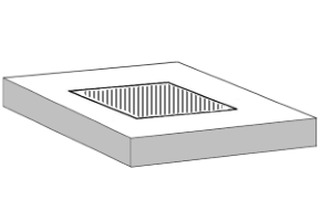
DROP GRATE INLET

Drop grate inlets can be in either sag or on-grade locations which means there can be bypass flows associated. These inlets are typically used in parking lots or open lawn spaces when in sag locations. Use in drainage swales, bar-ditches or v-shaped gutters in on-grade situations. Compound cross-slopes are not used, i.e. Sw is not a required input.
Opening Area
Enter the clear opening area of the grate. Required only in sags.
Grate Width & Length
Enter the width and length of the grate. Must be <= Gutter Width.
Set the Length to zero for automatic design. The program will size the inlet length for 100% capture. When Stormwater Studio designs for grates in sags, including combination inlets, it sizes the grate opening area using the “Grate Design Depth” in the Ribbon menu Inlet Design tab.
GENERIC INLET
 Use this inlet type if none of the other inlet types here work for your particular situation. It’s good if the inlet type is not important and you already know what the capacity is, or if you want Stormwater Studio to design a capacity for you.
Known Capacity
This is the only required input. For example, if this generic type has a known capacity of 3 cfs, the program will bypass 1 cfs if the Q catchment plus Q carryover equals 4 cfs.
Generic inlets are not intended to be used in sags so you will need to specify a longitudinal slope. When the Known Capacity is less than the total Q, the program will bypass the excess to the Bypass Line.
To have the software set the capacity for you, set the Known Capacity input to zero.
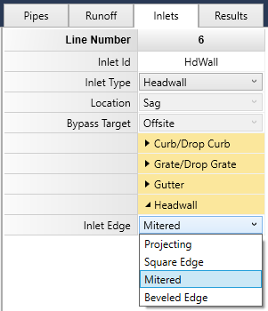
HEADWALL
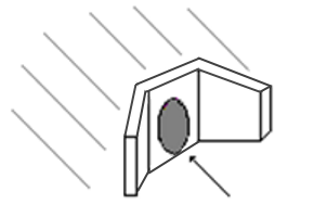
Open head walls do not require gutter or inlet input data besides the Inlet Edge. Your choices are:
- Projecting (default)
- Square Edge
- Mitered to Slope
- Beveled
Select an inlet edge from the drop-down list box under the Headwall group. Headwalls capture 100% of the flow. Enter the Surface elevation as it corresponds to the top of the headwall. Do not attempt to use this junction as an outfall.
Inlet & Outlet Control
Headwalls have a unique feature in that they will be automatically calculated using Inlet and Outlet Control concepts. The calculation option, “Check for Inlet Control” must be checked On for this feature to be utilized. When On, the program employs the HDS-5 methodology and uses your selected Inlet Edge.
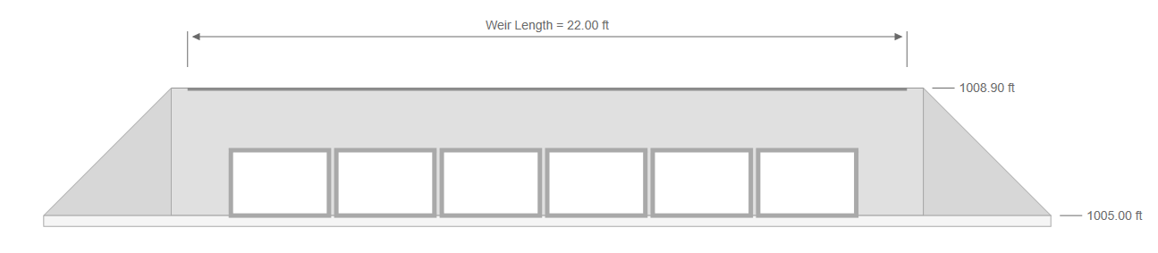
Overtopping Weir
Any Headwall structure can contain an overtopping weir to assist in modeling low-flow culverts with roadways. The software will include graphics that detail the Plan view, Surface view as well as Profile views.
To add a weir to your headwall structure, simply choose “Yes” on the Overtopping Weir dropdown list box.

The weir has only two inputs. One is already set and is equal to the Surface Elevation at the upstream end of this Line. This surface elevation serves as the weir’s crest.
- Weir Elevation – This is the elevation of the crest and must be above the top of the pipe. Once the water surface elevation exceeds the weir elevation, overtopping flow occurs. Note that this item is automatically input and is equal to the upstream Surface Elevation for this Line. The input here is disabled and is simply shown for your reference. To edit the Weir Elevation, edit the Ground Surface on the Pipes input tab or modify the Rim Elevation on the interactive toolbar while viewing a Profile.
- Weir Length – This is the total length of the weir crest.
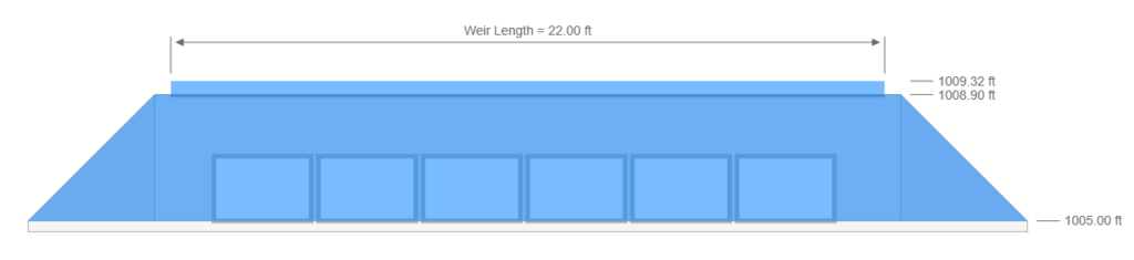

The weir crest will match the ground surface in profile. Keep in mind that the crest profile, or slope, has no affect on the weir flow amount.
When using a TIN surface, the crest will connect the most upstream and downstream ground points in a straight line. You can edit the actual Weir Elevation when a TIN Surface is present by modifying the Rim Elevation on the interactive toolbar while viewing a Profile.
The software employs an iterative process to determine the exact amount of weir and pipe flow. (Please see Computational Methods for a complete discussion.) The specific amount of weir flow can be found on the Inlets Report under the Bypass column.
IMPORTANT: Weir flow is not eligible to be used as carryover flow to other inlets. Rather it rejoins the pipe flow at the downstream end. From there the total Q will move to the next downstream Line as usual. A Bypass Target Line cannot be specified.
NONE
Select “None” when you need to connect two pipes without the use of a traditional junction. This may be useful for modeling pipes on horizontal or vertical curves. Simply make them a series of straight lines using this junction type. Energy losses are taken into account based on the deflection angle.
New to this site? Learn more about Hydrology Studio’s complete suite of stormwater design software.
- Hydrology Studio
- Stormwater Studio
- Culvert Studio
- Channel Studio
- Studio Express
Visit Hydrology Studio today.