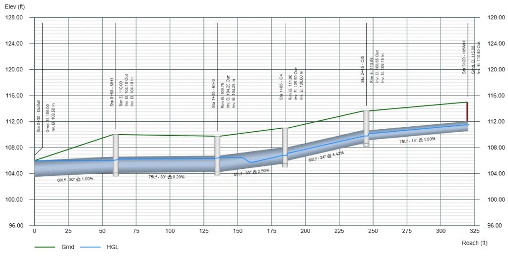
Once you have entered your Line data you are ready to calculate results. This is initiated by selecting the Compute tab on the Ribbon menu and clicking the [Run] button.

Prior to initiating the computation process by clicking Run, it is essential to carefully examine the range of options provided by Stormwater Studio for analyzing your system. It is important to note that the main objective of this computation is to derive different hydraulic parameters, all of which are dependent on the flow rate, Q.
Choose the Return Period
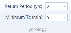
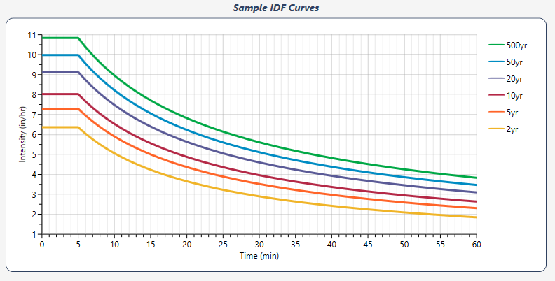
Hydrology options allow you to choose the return period as well as set the smallest Tc that will be used when accessing your IDF curves. If you are using Known Q’s exclusively, you may choose “None” for the Return Period. If you are employing the Rational method in your model, be sure to select a valid Return Period or you will get zero Qs for those Lines.
Calculation Options
There are a variety of methods and options to use when computing the results. These options are selected from the Calculation Options category on the Ribbon Menu.
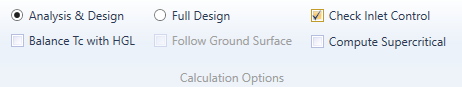
You have two primary calculation methods to choose.
1. Analysis & Design
This setting is the default and will be the most commonly used. It is suitable for both new and existing systems. The option will initially calculate the flows in the pipe system. It will then analyze and design from the downstream up, retaining all existing data such as pipe sizes and invert elevations that you have input. Any data that has been designated as zero for design purposes will be re-designed by the program as needed.
This option is ideal when downstream constraints are a priority, when working with existing systems, or when addressing deficiencies in a system. Keep in mind that this method operates from the downstream up and does not consider the Minimum Cover constraint.
Balance Tc with HGL
When employing the Rational method, this computation feature aids in resolving conflicts between the time of concentration and the ultimate hydraulic grade line (HGL). Typically, storm sewers are engineered to operate at full capacity. This is deemed appropriate as the pipes are sized and slopeded to correspond to a specific flow rate and velocity. Consequently, the cross-sectional area, A, of the pipe is presumed to be full.
The HGL needs to be computed in order to determine the actual area and velocity when analyzing existing systems. The computed Q’s are derived from assumed pipe velocities and an assumed Tc. The resulting HGL is also dependent on these assumptions.
In cases where the assumed velocity does not match the actual velocity, the calculated Tc will be inaccurate, leading to incorrect values for Q and resulting HGL. This solution addresses the issue by recalculating the HGL using actual flow rates and Tc values. Stormwater Studio performs multiple system iterations to ensure that the calculated Tc values closely align with the initially assumed values.
If you’re finding Lines in your results with extremely large System Tc’s and low Velocities, re-compute with this option checked ON.
Stormwater Studio initially calculates the HGL using Tc’s derived from full-flow velocity, followed by a second calculation using Tc’s based on actual velocities. Although the new velocities are more accurate than the initial trial, they are still incorrect due to being based on the original HGL calculation. With multiple system iterations, the Q’s, Tc’s, and resulting HGL gradually converge to the correct values. Stormwater Studio employs three iterations for this purpose.
If you’re finding Lines in your results with extremely large System Tc’s and low Velocities, re-compute with this option checked ON. Most likely you have a pipe assumed to be flowing full with a very small Q causing an extremely long pipe flow time, adding to the total Tc. Time = Pipe Length / Velocity.
2. Full Design
Use this option for new designs. Unlike the “Analysis & Design” option, this approach starts setting pipes at the upstream end and progresses downstream. It is important to note that this option requires inputting surface elevations for all Lines.
When utilizing this option, Stormwater Studio will reset all pipe sizes and invert elevations to zero and redesign the entire system. It will initially size the pipes based on the specified minimum and maximum pipe sizes, as well as the minimum velocity. It will then calculate the invert slopes.
Subsequently, it will set the invert elevations as high as possible, while always ensuring they remain below the specified minimum cover. At junctions, the outlet invert elevation is determined by the lowest surface elevation.
The Full Design option should be used when upstream constraints are significant and when designing new systems. It is important to remember that this method sets pipes to work from the upstream down and adheres to the minimum cover constraint.
Follow Ground Surface
This option will force the pipe slopes to follow the ground surface rather than the theoretical slope produced by Manning’s equation. This reduces the usage of drop structures, minimizing excavation costs. Pipe slopes are designed not to exceed the Maximum Slope set in the Ribbon menu Pipe Design tab.
Check Inlet Control
This option will automatically compute the headwater, Hw, using HDS-5 methodology for all upstream Junctions or Inlets that are designated as a Headwall, including those with overtopping weirs. It compares Hw with the computed HGL Junction using outlet control. The higher of the two will be used as the final “HGL Junct”. The outputted values will be appended with “ic” or “oc” representing Inlet Control and Outlet Control respectively.

Compute Supercritical Profile
Turn this on if you’d like the program to check for and compute a supercritical flow profile. (Only available for circular or rectangular pipes and open channels.) Learn more about supercritical profiles in the Computational Methods.
Junction Loss Options

The software provides three different methods to compute junction losses:
HEC-22 – The software will calculate losses at all junctions (excluding Headwalls with Inlet Control) using the 3rd Edition of HEC-22. It considers entrance losses, exit losses, and adjustments based on benching, angles of incoming lines, and plunging flows.
AASHTO – This method is based on the 1991 method developed by AASHTO. Similar to HEC-22, it addresses entrance, exit, bend, and plunging losses, with credit given for structure shaping. Additionally, when using the AASHTO method, a dedicated report is generated on the Reports tab that resembles the VDOT LD-347 report.
None – Select this option to exclude the calculation of minor energy losses at upstream structures.
Please see Junction Loss Computational Methods for details.
Design Options
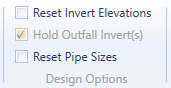
As described above in Analysis & Design, the program will fill in or design any pipe size or invert elevation that has been set to zero. These design options allow you to reset those items without having to individually edit them. In addition, It allows you to preserve the downstream invert at Outfalls. Only use these options when employing Analysis & Design. Full Design resets them anyway.
For example, if your system is already designed from an invert elevation standpoint and you’d like to re-size the pipes, check “Reset Pipe Sizes” and re-compute using Analysis & Design. The result will hold the existing Inverts, but will resize the pipes.
Note that Design Options uncheck themselves after each use.
Flow Options
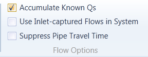
Accumulate Known Q’s
Known Qs can be introduced into any line of your system. This feature accumulates these known Qs as the program works downstream, if checked. If unchecked, known Q’s are not summed.
Use Inlet Captured Flows in System
Inlet flow quantity calculations are done separately from system flows. In other words, most designers, and Stormwater Studio, assume that all of the flows (100%) computed by the Rational method will enter the pipes. The HGL calculations will be based on those flows. If checked, this option limits the pipe flows to those actually captured by the inlets. This option should typically be in the OFF position but is helpful when analyzing an existing system.
Important! If the junction is not an inlet (Manhole or None for example) it cannot capture inlet flows, resulting in a zero Q. If a Line has a Drainage Area, C and Inlet Time, its junction type must be an inlet when this option has been checked On. Also note that if the Total Q’s shown on your reports don’t match the corresponding Q = Cia, this option has most-likely been checked On.
Suppress Pipe Travel Time
Turn this feature on if you want the calculations to ignore travel times in pipes when computing Tc for the system. This may be useful when the system may contain an unusually long pipe, skewing the System Tc.
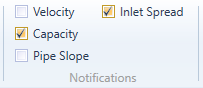
Notification Options
Why are my Lines and Inlets colored yellow?
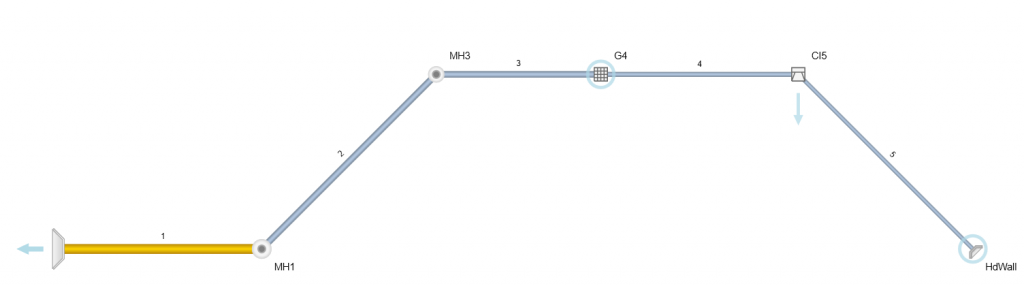
Stormwater Studio will change Line colors, highlighting any Line or Inlet to a bright yellow color, when certain criteria have not been satisfied and it’s corresponding Notification option has been turned On. For example, you can have any Line in your system highlighted whose flow rate is above the calculated Full-flow Capacity.
Keep in mind that it is usually okay for a Line to have a higher Q than its theoretical full-flow Q. It’s the final HGL and EGL that should determine if the Q is acceptable.
Other options include Velocity (Min and Max) and Slope as set in the Pipe Design tab and the Max Spread as set in the Inlet Design tab. When any of these criteria are violated, the Line or Inlet is highlighted. Max Spread only applies to Curb, Grate and Combination inlets.
To activate the various notifications, check or uncheck these options located on the Compute tab.