
As described in the previous topic, bridge sections are added just like any other channel section. Just click on the Bridge/Culvert Section button on the side tool bar on the Model tab and choose “Add Bridge Section”. Move your mouse to the desired river station and click your mouse. Then click the [Ok/Select] button or press [Esc] when finished.
A typical model layout containing a bridge section will look like this on your Model tab:
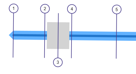
Bridge Section Data
It’s important to note that bridge, culvert and weir sections do not require Geometric (Station, Elevation) Data. Rather they inherit the data from the previous downstream section. For example, in the model shown above, Bridge Section 3’s geometric data will be bound to Section 2, including n-values and overbank stations.
If abutments are specified, the program will instead use n-values associated with what was specified in Project Settings for Concrete, in the Right and/or Left Overbank areas. Not what was entered in the downstream bounding section.
All that’s needed are inputs pertinent to the structure itself which are described below.
Name
Optional but it is a recommended input.
Downstream Distance
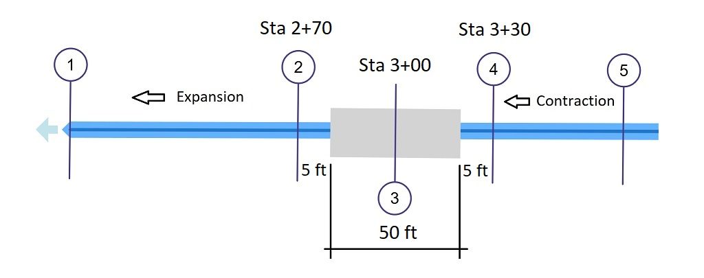
Enter the distance from the downstream channel section to the downstream edge of the bridge deck. In the plan view shown below, it’s the distance from Section 2 to the downstream end of the Deck, i.e., 5 feet.
Bridge Deck
Deck Width
Enter the width of the bridge deck in the flow direction. (This is not the length from the left side of the channel to the right but the width across the lanes.) In the example above, the Deck width is 50 feet.
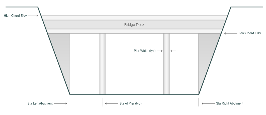
High Chord Elevation
Enter the elevation of the top of the bridge deck. This elevation will be used to trigger overtopping flow. The distance between where the high chord intersects the channel banks is what is used as the weir crest length during weir flow calculations.
Low Chord Elevation
Enter the elevation of the bottom of the bridge deck. This must be below the highest point(s) of the cross-section data. When the water surface exceeds this elevation, the lower deck length is added to the wetted perimeter.
Bridge Abutments
Bridge abutments are optional and may be on a slope. Vertical abutments will have a zero slope. Abutments play a primary role in establishing ineffective flow areas.
Station Left, Right
Enter the stations where the abutments intersect the channel bottom. If using abutments, the program will replace the overbank n-values with the v-value for concrete in Project Settings. Because of this, you should be sure to set the Left and Right Overbank stations of the bounding, downstream cross-section to match the abutment stations.
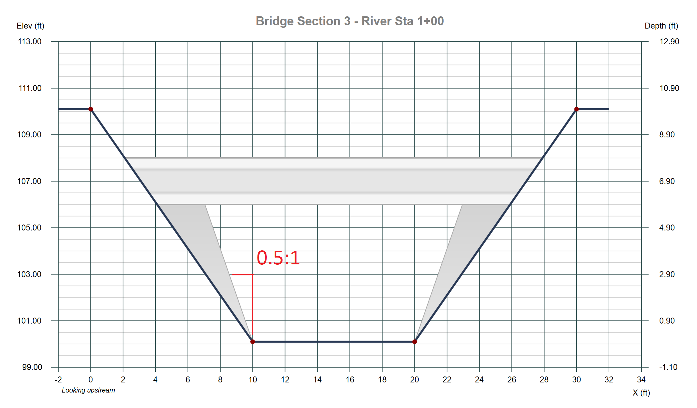
Slope (H:1)
Enter the slope of the abutments as horizontal to 1 vertical. For example, for a 3 horizontal to 1 vertical slope, enter 3. This value is used for both left and right sides and must be >=0.
Bridge Piers
Piers are optional. You can enter up to four, each with unique station locations and widths. Submerged piers are subtracted from the cross-sectional area of flow and will also increase the wetted perimeter.
Station
Enter the station location of the pier.
Pier Width
Enter the width of the pier.
Bridge Scour
The software will automatically compute contraction and pier scour provided the following inputs. See also, Evaluating Bridge Scour.
Bed Material, D50
Enter the median diameter of the bed material, diameter which 50% of the sizes are smaller, inches or mm. If this item is left blank or set to zero, scour calculations will not be performed. A typical value for sand is 0.012 inches.
Pier Nose Shape
Used for pier scour calculations only. Select the shape of the pier from the drop-down list box. Default is Rounded.
Apply the Data
To accept your inputs, click [Apply]. If you are modeling bridge abutments, Channel Studio will immediately set up ineffective flow areas for the downstream and upstream sections if “Auto Ineffective Flow Areas” option is checked on the Compute Tab – Calculation Options.