
Channel Studio utilizes the computational techniques outlined in Hydrologic Engineering Circular No. 18, (HEC-18) to conduct scour calculations. Once the water surface calculations are completed, the software automatically computes the scour if the Scour input for D50 has been provided. No additional input is required from the user.
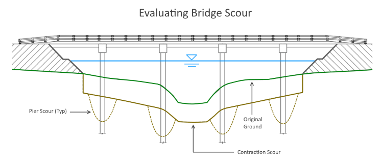 The software computes two types of scour:
- Contraction
- Pier
Both are described below.
Contraction Scour
Contraction scour is evaluated using two basic equations:
- Live-bed
- Clear-water
Live-bed contraction scour happens when bed material is moved from the upstream approach section to the bridge cross section. During live-bed scour, the contracted section under the bridge expands until the sediment transported out matches the sediment brought in.
Clear-water contraction scour can happen in two scenarios. The first scenario is when there is no movement of bed material from the upstream reach to the downstream reach. The second scenario is when the material being transported in the approach section is carried through the bridge section in suspension.
If there is a flow of bed material in the approach section upstream of the bridge, it is considered as live-bed flow, and the Live-bed equation is applied. On the other hand, if there is no transportation of bed material, it is referred to as clear-water flow, and the corresponding equation is used. To ascertain the prevailing condition, it is necessary to calculate the critical velocity, which is the velocity at which bed material starts to transport.
Critical Velocity
Critical Velocity is computed using the following equation:
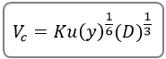
Where:
Vc = Critical velocity in ft/s (m/s)
Ku = 11.17 English (6.19 SI)
y = Average depth of flow upstream of the bridge, ft. (m)
D = D50 in ft. (m)
If Critical velocity is greater than or equal to the Average velocity in the upstream approach section, the Clear-water equation is applied. Otherwise, the Live-bed equation is utilized. Our observations indicate that the Live-bed equation typically results in greater scour compared to the Clear-water equation, with no discernible transition zone. Consequently, minor adjustments in D may lead to significant variations in scour depths.
Live-bed Equation
The Live-bed equation is utilized as needed for each sub-area, i.e., the Left overbank, Main channel and Right overbank.
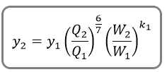
Where:
y2 = Average depth in the contracted Bridge section after scour, ft (m)
y1 = Average depth in the upstream approach section, ft (m)
Q1 = Flow in the upstream approach section transporting sediment, cfs (cms)
Q2 = Flow in the bridge section, cfs (cms)
W1 = Bottom width of the approach section that is transporting bed material, ft (m)
W2 = Bottom width of bridge section less pier width(s), ft (m)
k1 = Exponent based on the Fall Velocity of the bed material, D50. Can be 0.59, 0.64 or 0.69
Clear-water Equation
The Clear-water equation is utilized as needed for each sub-area, i.e., the Left overbank, Main channel and Right overbank.
Where:
y2 = Average depth in the contracted Bridge section after scour, ft (m)
Q2 = Flow in the bridge section, cfs (cms)
W2 = Bottom width of bridge section less pier width(s), ft (m)
C = 130 for English and 40 for SI units
Dm = 1.25 x D50
Scour Depth
The actual scour depth, ys, is computed as:
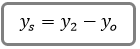
Where:
ys = Average depth of scour in ft (m)
yo = Average depth under the bridge (area of flow / top-width) before scour in ft (m)
The bottom widths of sections (W) are approximated by using the computed water surface top widths.
Pressure Flow Scour
When the water surface at the upstream end of the bridge deck is above the low chord of the deck, pressure flow exists. In these cases a distance, t (separation zone thickness), is added to the computed scour. The distance t is measured from the low chord elevation to the water surface at the downstream end of the deck.
Pier Scour
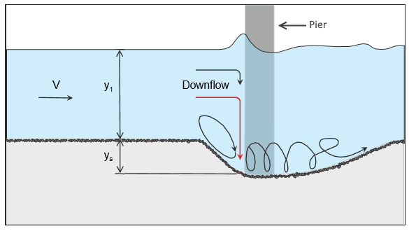
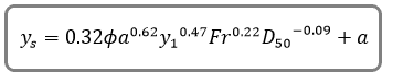
Channel Studio uses an equation developed by Dr. David Froehlich, 1991 for computing local pier scour. This equation is used in lieu of the HEC-18 Colorado State University equation due to its simplicity. This equation is also used as an alternate in HEC-RAS.
Where:
Ø = Correction factor for pier nose shape – 1.0 rounded; 1.3 square; 0.7 triangular
a = Projected pier width with respect to the direction of flow
Fr = Froude number
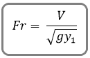
Where:
V = Average velocity across the bridge section at the upstream side
y1 = Average depth of flow just upstream of the individual pier
It should be noted that the additional + a (one pier width) at the end of this equation is simply a factor of safety recommended by Froehlich when designing. Channel Studio does not include this in its calculations.
The Pier Scour width is equal to 2 x Ys, to each side of the pier.
Pier Scour Limits
If the Froude Number, Fr, is <= 0.8 then the maximum pier scour depth is 2.4 x Pier Width. If greater than 0.8 the maximum pier scour width is 3 x Pier Width.