
Stormwater Studio uses the energy-based Standard Step method when computing the hydraulic profile. Flows are steady. This methodology is an iterative procedure that applies Bernoulli’s energy equation between the downstream and upstream ends of each line (Pipes and Channels) in your system. It uses Manning’s equation to determine head losses due to friction.
Losses at junctions are computed using the methodology prescribed by HEC-22, 4th Edition or the AASHTO method. It will use FHWA HDS-5 methodologies at upstream headwalls for inlet control.
The greatest benefit to using this method is that a solution can always be found regardless of the flow regime. This method makes no assumptions as to the depth of flow and is only accepted when the energy equation has balanced.
The following equation is used for all flow conditions:
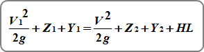
Where:
V = velocity in ft/s (m/s)
Z = invert elevation in ft (m)
Y = HGL minus the invert elevation in ft (m)
Friction losses are computed by:
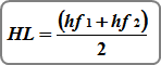
Where:
HL = energy head loss
hf1 = friction head at the downstream end
hf2 = friction head at the upstream end
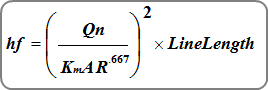
Where:
Km = 1.486 (1.0)
n = Manning’s n
A = cross-sectional area of flow in sqft (sqm)
R = hydraulic radius

Calculation Procedure
Stormwater Studio computes the energy and hydraulic grade line in a fashion similar to methods used for open channels. The program begins computing at the most downstream line and works in a standard step procedure upstream. This method assumes the starting hydraulic grade line elevation, HGL, is known. In other words, you may specify a starting tailwater elevation.
Tailwater Elevation
Stormwater Studio will use this entry as the starting water surface elevation when computing.
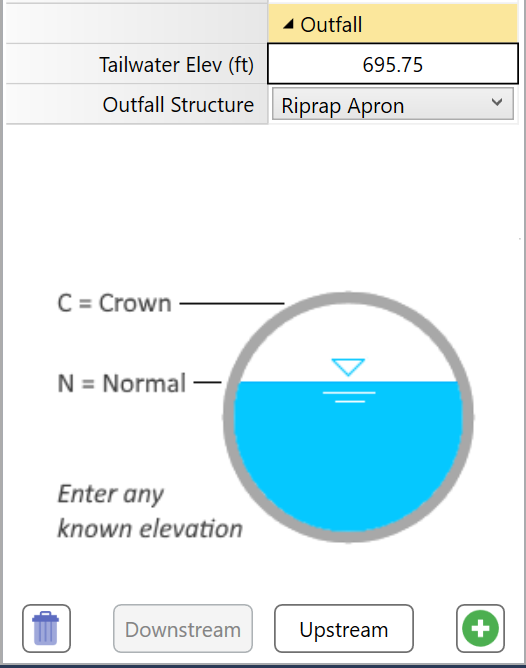
You have three options:
Known Elevation – Enter a known starting tailwater elevation.
Water surface profiles, initially, must begin at or above critical depth in order to achieve a proper energy balance.
Crown – The is the default setting. This elevation will begin at the top of the pipe. To choose Crown, simply enter a blank value, zero, or the letter “c” or “crown” (no parentheses).
Normal – This will compute normal depth for the pipe and use it for the Tailwater Elevation. If normal depth is less than critical depth, then critical will be used instead. To choose Normal, type in the letter “n” or “normal” (no parentheses).
An upstream HGL is assumed for a given Line and is then checked against the energy equation. If the energy equation does not balance, another HGL is assumed and the iterative process continues until the assumed HGL equals the computed HGL.
Junction Losses
Stormwater Studio computes losses at junctions automatically and uses the selected methodology on the Compute tab. For complete details, please see Storm Sewer Junction Losses.
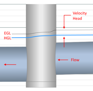
Starting HGL for Upstream Lines
The initial EGL for the incoming upstream Line(s) is determined by adding the computed EGL of the downstream Line with any losses at the junction. This value serves as the starting EGL for these incoming Lines. To calculate the starting HGL, the velocity head is subtracted from the EGL Dn. By employing this approach, any energy disruptions that may arise, such as pipe size reduction in the downstream direction, increased pipe slope, or significant alterations in flow rate or inverts across the junction, are effectively eliminated.
However, if the starting HGL at the downstream end of any Line (except outfalls) is below Normal Depth, Normal Depth will be the new starting HGL. In the case of steeply sloped pipes where Normal Depth is less than Critical Depth, Critical Depth will be used as the starting HGL.
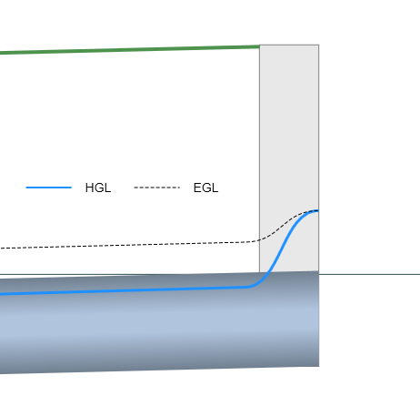
Losses at Headwalls
Pipes with Headwalls at their upstream ends can flow under two regimes;
- Inlet Control
- Outlet Control
Inlet control suggests that water faces greater difficulty entering the pipe than flowing through it. Conversely, outlet control indicates that it is harder for the flow to pass through the barrel than to enter it.
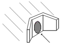
Inlet control is largely influenced by the entrance geometry of the pipe such as edge configuration, pipe area and shape. Outlet control is influenced most by n-value (barrel roughness), pipe area, shape, length and slope.
Stormwater Studio computes the hydraulic profile assuming both exist, and then selecting the one that produces the highest headwater. This is designated on the reports under the HGL Junction column. The values will be appended with either “ic” or “oc” indicating Inlet Control or Outlet Control respectively.
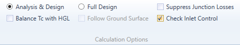
Note that the calculation option, “Check for Inlet Control” must be checked On for this procedure to take place. If Off, only outlet control will be considered and there will be no “ic” or “oc” appendages.
Outlet Control
Outlet control is always calculated for the Headwall junction type as described in Energy Grade Line.
Inlet Control
During inlet control procedures, the following inlet control equations are used. If Hw is above the pipe crown the submerged equation is used. Otherwise the unsubmerged equation is used.
Submerged Condition
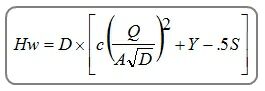
Unsubmerged Condition
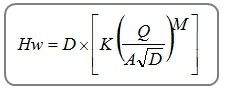
Where:
Hw = Headwater depth above invert
D = Pipe’s Rise in ft (m)
Q = Flow rate in cfs (cm/s)
A = Full cross-sectional area of pipe in sqft (sqm)
K, M, c, Y = Coefficients based on inlet edge configurations per HDS-5
S = Line slope, ft/ft (m/m)
It is assumed that the pipe material matches the selection on the Home tab under the Pipe Color option. The above procedure follows the FHWA HDS-5 methodology.
Want to learn more? See, Water Surface Profiles for Storm Sewers in Further Reading for an in-depth article on this topic.