
Stormwater Studio has the ability to add TIN (Triangulated Irregular Network) maps to your project. This is a layer that can be added in addition to background maps. You can add up to two separate TIN surfaces concurrently; one representing the proposed and another for existing conditions. Your RIM/Surface elevations of your storm sewer Lines will automatically connect to Proposed TIN Surfaces, but not Existing TINs. In addition, TIN Surfaces will have no effect on Open Channels in that it does not connect any inputs to the TIN surface. TIN Surfaces can be imported only in a LandXML-formatted file. Most CAD software supports LandXML and typically offers the option to export a TIN Surface to LandXML.
What is a TIN Surface?
A TIN is a vector-based representation of the physical land surface and is constructed by triangulating a set of 3-dimensional points, consisting of a Northing, Easting and Elevation. The points are connected with a series of edges to form a network of triangles. Within each triangle the surface is represented by a plane. TIN models allow extra data in complex areas and less data in non-complex areas thus making them more economical than traditional raster type DEM models.

A TIN Surface is different from a background map in that it is dynamic. That is, it (the Proposed Surface) will automatically set your storm sewer Surface/Rim Elevations to match the TIN Surface. If the location of your Line(s) change, so do the Rim Elevations.
When a Proposed TIN Surface is loaded you’ll never have to enter Rim Elevation for your storm sewer lines. In addition, any of the Surface TINs will automatically generate intermediate ground points between junctions for use in your Profiles. The TIN Surface also works when you import Lines from a DXF or LandXML PipeNetwork.
You can import Lines or a TIN Surface in any order you wish. It is recommended, however, that you import your TIN(s) prior to adding Lines.
How to Import a TIN Surface
TIN Surfaces are imported from the Plan tab only. To import, click on the TIN Surface button on the side toolbar. Then select “Existing” or “Proposed”. These can be imported in any order you wish.
![]()

Next, browse to the .XML file which contains your TIN Surface and click [Open]. Stormwater Studio will parse the file searching for available Surface Elements. Afterwards, you’ll be presented with the following screen:
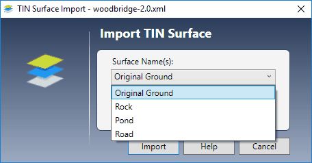
Here you can select a single Surface TIN from the drop-down list box. (You can only add one surface). Click the [Import] button.
A message box will first appear informing you of the number of points and triangular faces contained in the file. Click [Ok] and in a few seconds the TIN will be displayed on your Plan tab as shown in the example below.

Any existing Lines in your project will be updated to match the Proposed TIN Surface. New lines added will also be attached to the TIN Surface. The Existing TIN Surface will not affect the RIM/Surface elevations.
The status bar at the bottom of your screen will display the Surface Name(s) as well as the TIN’s elevation at the X, Y location of your mouse.
Cut/Fill
If you have both Proposed and Existing TINs loaded, the status bar will show the difference between these surfaces, i.e., Proposed elevation minus Existing elevation at the current mouse location. Positive values will be labeled as “Fill” and negatives as “Cut”.
Large TIN Files May Be Slow to Draw
While most TIN Surfaces used for site design contain around 1,000 to 5,000 points, some can easily exceed 100,000. Depending on your computer’s graphics hardware, large TIN files will require a lot of time to render and can slow down your ability to work with your project. This becomes noticeable when the number of points exceed 5,000. Stormwater Studio has a set limit of 10,000 points and will not load files that exceed that limit. It will provide you with a notice when that occurs. There are two things you can do to help with large TIN files:
- If it exceeds the point maximum, try to re-export the TIN Surface from your CAD software as a more “simplified” version with fewer points.
- Use the small cursor setting in the Plan Layout Options located on the Home tab.
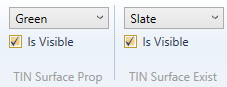
- Once you have opened a TIN Surface and it is displayed but slow to draw, you can hide the TIN by checking OFF the “Is Visible” property on the TIN Surface options located on the top ribbon menu. This will effectively prevent the TIN Surface from being drawn but the TIN will remain fully functional behind the scenes. Turn “Is Visible” back ON from time-to-time to take a peek if desired.
Plotting Profiles That Use a TIN Surface
You can plot profiles for any single or a selected set of Lines just as you normally do. But when a TIN Surface is present, you will see a series of intermediate ground points between each junction. These ground elevation points are calculated from the TIN Surface where a straight line connecting the junctions intersects the triangular faces. The more faces in between junctions, the more ground points. When a junction does not fall exactly on a face line (rarely does) it uses barycentric coordinates to compute the elevation.
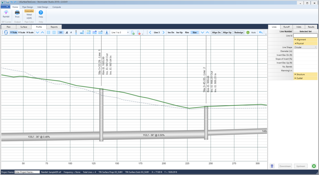
The Proposed ground surface will plot as a solid green line and the Existing as a gray dotted line.
Overriding the TIN Surface
There may be occasions when you will want to manually set the RIM Elevation(s) of a particular junction, overriding the Proposed TIN Surface. For example, the Rim Elevation may need to be lowered to match the invert of a curb-style inlet, or be raised to a pre-defined finish elevation, etc. However, when a Proposed TIN Surface is present, the input fields for the Line Surface/Rim Elevations are “Read Only” and cannot be edited directly.
You can manually set the Rim Elevations on the Profile tab by selecting the Line and the Rim input on the Interactive Toolbar. Adjust Up/Down using the Arrow buttons to the desired elevation. The software will preserve the adjusted elevation until you edit (move, delete, insert) the location of the junction or connecting junctions on the Plan tab.
Removing a TIN Surface
You can remove and disconnect your TIN Surface at any time by clicking the same TIN Surface button on the side toolbar that you used to originally load them.
![]()
You will be prompted to “Clear” the existing TIN or cancel. Once removed, the existing Proposed TIN-based Surface/Rim elevations will remain but the intermediate ground profile points will be discarded. You will then be able to edit the Surface/Rim elevations for each Line manually.
Saving Projects Containing TIN Files
Stormwater Studio basically extracts only the data necessary from the TIN file(s) and discards the rest. This data is then saved inside of your project file. It reloads the next time you open the project file. There’s no need to manually manage the TIN Surface data. The original TIN .xml file remains as-is and intact.