The process of routing a hydrograph through a detention pond closely resembles the use of other processing functions such as Junction, Channel Reach, or Divert. To initiate this, you select an existing “Inflow” hydrograph and then click the [Route] button.
The Inlow hydrograph can be any existing hydrograph, including runoff, channel reaches, junctions and even previously pond routed hydrographs.
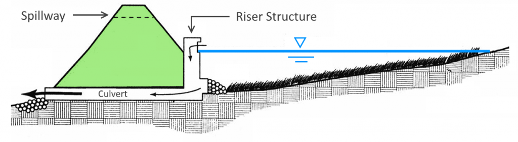
It is important to ensure that there is an existing pond available for routing prior to clicking [Compute]. See Creating Detention Ponds for a complete discussion on creating and designing a detention pond.
Although you might have utilized the Trial Route feature in the Pond Designer, it is essential to conduct the actual routing in the Main Window. After establishing at least one pond, you can route any existing hydrograph through it. Please note that you can only specify a single inflow hydrograph. If multiple inflows are required, they must be combined using the Junction process beforehand.
To route a hydrograph, begin by selecting the “Inflow” hydrograph. You can do this by either dragging a rectangle around it using your mouse or by clicking on the designated icon.
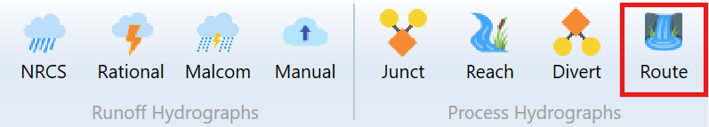
 Then click the [Route] button on Ribbon Toolbar.
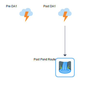
A Pond Route icon will be incorporated into your model, resembling the example provided. It is important to understand that the Pond Route icon signifies the hydrograph for the pond-routed outflow, rather than the pond itself. The pond serves merely as one of the input parameters.
Next, click on the Route icon to populate its input window.
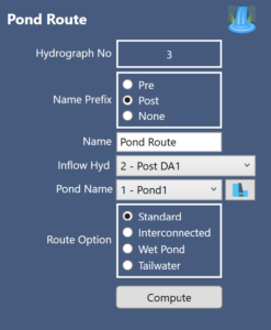
Required Data
The following is a description of each of the required input items.
Name Prefix
You can include a prefix (“Pre”, “Post” or nothing to your hydrograph Name field with a single mouse click. This saves precious keystrokes when doing a pre- and post-development study and you want to identify those hydrographs that are “Pre” or “Post” development. The chosen prefix will be added to the front of the Name label on the Basin Model and throughout the software, for example, Tables, Charts, Reports, etc.
Name
Enter any descriptive name for this hydrograph. It will appear on the printed reports as well as the Basin Model.
Inflow Hydrograph
The inflow hydrograph has already been selected but can be edited at any time. Just select from the drop-down list.
Pond Name
Select the pond you wish to use for this routing (Ponds 1 through 25) from the drop-down list. You can edit an existing pond or create a new one directly by clicking the adjacent Pond Edit button.

Your Routing Options
Hydrology Studio offers four separate routing options. You must create a pond prior to selecting a Routing Option.
1. Standard (default)
This option will perform a standard routing.
2. Interconnected Pond Routing
Use this option to perform an interconnected pond routing where an Upper pond flows into a Lower pond. (See Interconnected Pond Routing below for more information.)
Here you will be asked to specify the Upper and Lower Ponds as well as an optional additional inflow hydrograph into the Lower pond.
Upper Pond
Select an existing Upper Pond from the drop-down list box.
Lower Pond
Select an existing pond for the Lower pond. This pond cannot be the same as the Upper Pond.
Additional Inflow (applicable to Interconnected ponds only)
You can choose an additional inflow hydrograph to be added to the Lower Pond as long as this hydrograph was previously added to your Basin Model. Select the hydrograph from the drop-down list.
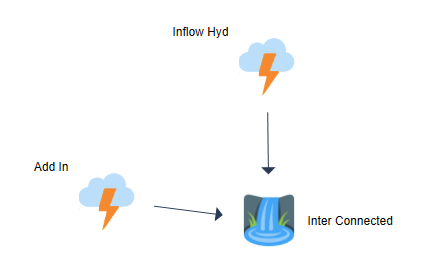
The additional inflow hydrograph must have a number greater than the primary inflow hydrograph and less than the outflow, routed hydrograph. In the example shown below, Inflow Hyd is Hyd No. 1, Add In is Hyd No. 2 and the Inter Connected is Hyd No. 3. Hydrograph Numbers must increase as you work downstream.
3. Wet Pond Routing
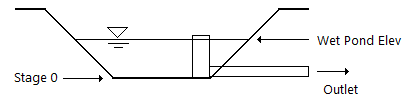
This feature enables you to navigate through a pond that contains a predetermined volume of water. Keep in mind that when designing this pond, you need to detail the entire pond, from Stage zero to the Top, not just the section that is above the water’s surface.
Select the wet pond water surface elevation from the drop-down list. Note that there cannot be outflow from the pond at this chosen wet pond elevation.
4. Variable Tailwater
This option allows you to specify fixed tailwater elevations for each active return period. Simply enter the tailwater elevation in the input grid. Note that any tailwater elevation that you may have used while setting up your pond will not be carried over to the final routing. You must specify your tailwater elevation(s) on this screen.
Click [Compute] when finished.
Interconnected Pond Routing
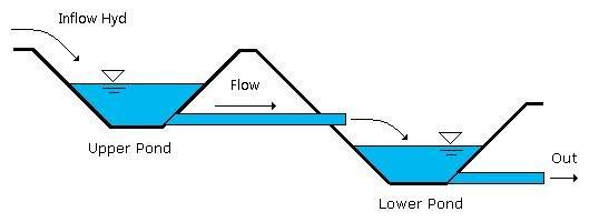
Utilize the Interconnected routing feature when you have two distinct detention ponds that need to be linked. Hydrology Studio is capable of routing any hydrograph through two interconnected ponds. There will be occaisions when you do not need to utilize the built-in interconnected pond routing function, but rather treat the two ponds separately.
When the Downstream Pond is Below the Upstream Pond
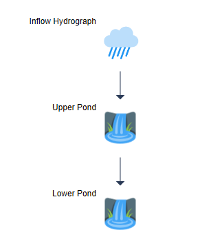
It is important to remember that the outflow hydrograph from an upstream pond can be directly utilized as the inflow hydrograph for the downstream pond. This approach involves performing two distinct routings rather than using the interconnected pond routing method. This is applicable when the lower pond is positioned significantly below the upper pond. The upper pond does not experience any backwater effects from the lower pond.
The Basin Model will look like this:
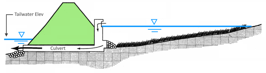
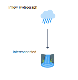
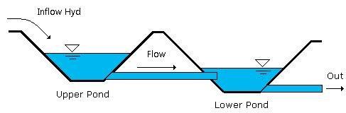
Downstream Pond is Near Same Elevation as the Upstream Pond
If the bottom elevation of the downstream Lower pond is comparable to that of the Upper pond, it may influence the stage-discharge relationship of the Upper pond. Consequently, this will impact the outflow hydrograph from the Upper pond. While this situation seldom alters the final outflow hydrograph of the Lower pond, it necessitates the use of an interconnected routing procedure.
In the Basin Model shown below, the Interconnected Hydrograph icon represents both routings (Upper pond through the Lower Pond).
Lower pond affects the Upper pond
Here is a Blog post about when and when not to use this feature. Routing Interconnected Ponds. Should You or Shouldn’t You?
Interconnected Pond Calculation Procedure
The routing process involves the dynamic connection of the two ponds. The calculations for routing are performed in discrete time intervals that correspond to the project’s specified Time Interval. During each interval, the outflow from the upper pond is directed through the lower pond. The resulting water level in the lower pond serves as the tailwater for the upper pond in the subsequent calculation interval. The stage-discharge curve is recalculated without any interpolation from the original curve. A new outflow is determined for the upper pond, and this procedure continues for the remaining time intervals.
Thousands of detailed computations take place during this procedure. Hydrology Studio’s fast and highly structured source code is demonstrated.
Although the program computes two hydrographs during this procedure, only the Lower Pond outflow hydrograph is available for further downstream processing. The Upper Pond hydrograph is attached to the lower (primary) hydrograph and will appear on all reports, graphs etc.
Only two ponds can be interconnected at once.
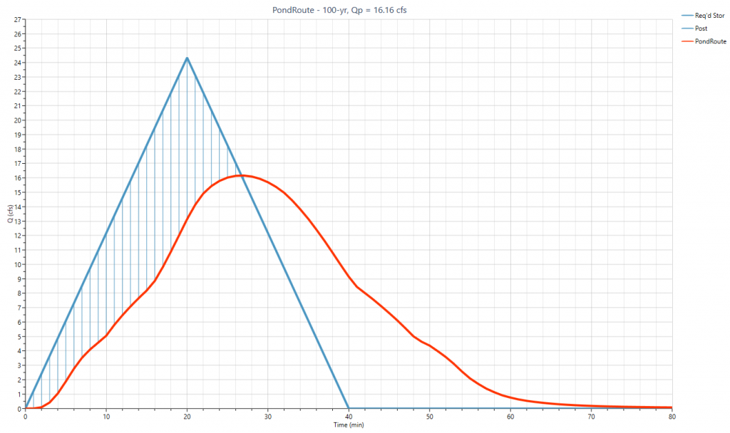
 The Upper pond’s outflow hydrograph is shown as a dotted line. The final outflow hydrograph is the solid red line.