Channel Studio allows for the incorporation of bridge crossings in your model. All cross-sections, with the exception of Section Number 1 and the final section, can serve as bridges. Bridge sections can be added to your model whenever needed by following the steps outlined in “Adding Cross-Sections”, but selecting the Bridge/Culvert section button and opting for “Add Bridge Section”.

Bridge sections can include:
- Elevations for top and bottom bridge deck (chords) (Required)
- Vertical or sloped abutments on either side of the bridge (Optional)
- Up to four individual vertical piers (Optional)
- Inputs for contraction and pier scour (Optional)
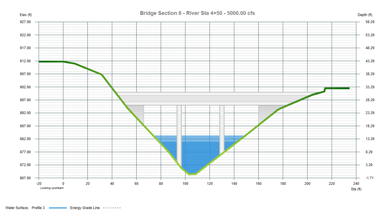
Hydraulic modeling is similar to that of the channel sections except the submerged area of abutments, piers and bridge deck are subtracted from the cross-sectional areas. Wetted perimeters are adjusted as well to accommodate the submerged structures including the lower bridge chord. The analysis also considers flow which may be overtopping the bridge, weir flow.
Energy losses are computed in 3 parts:
- From the reach immediately downstream of the bridge to the downstream edge
- Through the bridge structure itself to the upstream edge
- To the reach immediately upstream of the bridge
Therefore it is important to include cross-sections at these locations.
Locating Bridge Sections
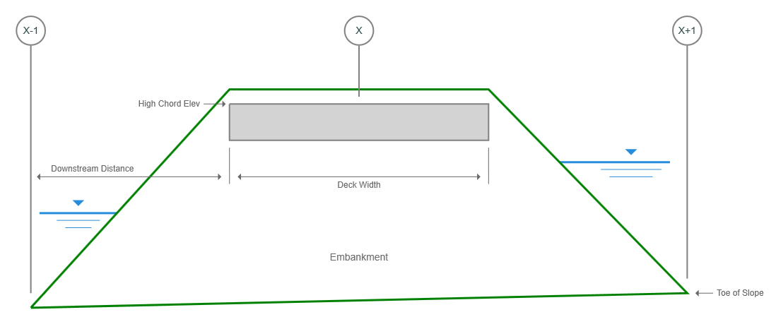
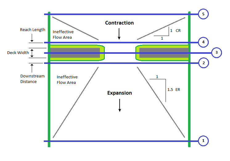
Each bridge crossing will need to have a Channel section located just downstream of the bridge and one just upstream as shown below. These sections are typically located at the toe of the bridge embankment and represent the natural channel adjacent to the bridge.
The Section at X-1 below is located at the “Downstream Distance” described below.
In addition, a proper model will also include those sections sufficiently downstream and upstream (Sections 1 & 5 in the figure below) to where the flow has fully expanded and is not affected by the structure. These sections become less important as the abutment side restrictions lessen.
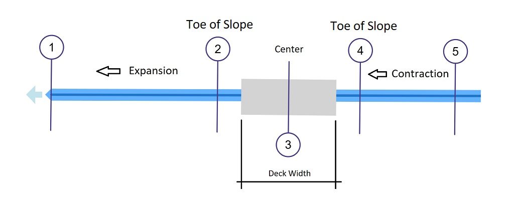
The Contraction Ratio (CR) as shown below is 1 while the Expansion Ratio is 1.5. These values are user-definable and are set/reset in Project Settings. They are used when automatically setting ineffective flow areas.
Procedure for Locating a Bridge
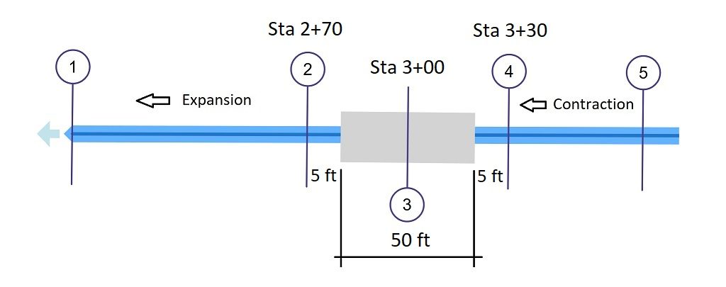
The best procedure for locating your bridge and related cross-sections is to plan ahead. First, determine the river stations of your sections. For example, given the following and the plan above:
Bridge is located at River Sta 3+00 (randomly chosen for this example).
Deck Width = 50 ft.
Downstream Distance is 5 ft.
Reach Length for Section 4 is 5 ft.
The Bridge Section is No. 3. Here’s where to place Sections 2, 3 & 4:
Section 2
At the centerline of the bridge (300′) minus one-half the deck width (50′) minus the Downstream Distance to Section 2 (5′). Sta 300 – 50/2 – 5 = Sta 2+70
Section 3 (the bridge centerline)
At Sta 3+00
Section 4
At the centerline of the bridge plus one-half the deck width plus the distance to Section 4.
Sta 300 + 50/2 + 5 = Sta 3+30
Next, just add them to your model at these river stations. Remember, you can always adjust the locations and reach lengths at any time either via the Model or by direct entry of the section data.
When making adjustments to section locations on the Model tab, Channel Studio will automatically set the reach lengths and downstream distances for you.