
By merging the model layout and geometric cross-section data, Channel Studio automatically produces a coordinate-based plan view like the one shown below. To view this, click the Plan tab.
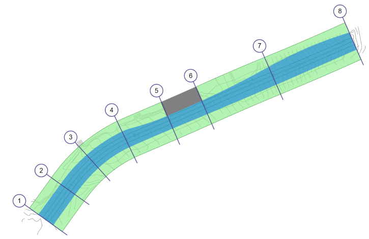
Plan maps can be exported for further processing. The green lines are the channel extents, overbanks and the channel centerline. If the inputs are current with the calculations, the water surface will be overlaid on top.
Like the Model view, you can zoom in/out using your mouse wheel. Pan by dragging your mouse in any direction.
Use the options located on the left to toggle on or off the Channel boundaries showing only the water surface.
Exporting Your Plan Drawing
You can export the Plan view in a variety of formats as mentioned above. To export, click the [Download] button on the side toolbar and choose one of the menu options.
![]()
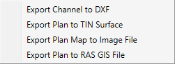
Note that the DXF and TIN Surface export options only include the channel and water surface. Because they are drawn schematically, bridge, culvert and weir structures are omitted. Exporting to a RAS-GIS file is only available after you have computed a water surface.
Exporting to a TIN Surface
One option that deserves particular attention is the TIN Surface. Channel Studio can save this image as a LandXML TIN Surface for which you can import into your CAD software which may have enhanced 3-D viewing capabilities. Before exporting, be sure that your cross-sections do not contain any duplicate Sta/Elev points as this will prevent the software from creating a proper TIN surface.
The Channel and Water Surface are saved as individual Surfaces for which you can assign different textures as shown below.
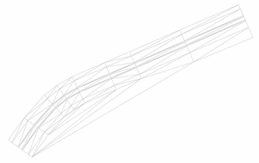
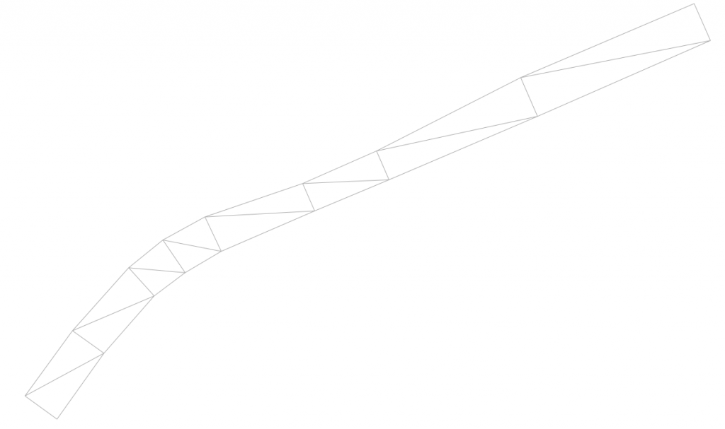
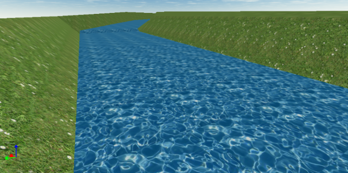
Combined TIN Surfaces as rendered in Carlson Precision 3D™