
Energy losses at upstream structures, although commonly referred to as minor, may not necessarily be insignificant. These purportedly minor losses have the potential to accumulate along the entire length of a storm sewer system and therefore warrant thorough evaluation.
Stormwater Studio provides two popular methods for computing these losses. We have found that both of these methods work equally well. When employing the AASHTO method, the software adds an additional dedicated report on the Reports tab that mimics VDOT LD-347 report.
- HEC-22 – This will compute losses at all junctions (except for Headwalls optioned for Inlet Control) using the 3rd Edition of HEC-22. Entrance losses including consideration for inlet and outlet control, exit losses, and other adjustments based on benching, angles of incoming lines, and plunging flows are calculated. Note that this method does not compute losses when the depth exiting a junction is at critical depth.
- AASHTO – This option uses the 1991-based method developed by the American Association of State Highway and Transportation Officials. While not as complicated as HEC-22, the AASHTO method similarly addresses entrance (expansion), exit (contraction), bend and plunging losses. Credit is also provided for structure shaping or benching.
- Suppress Junction Losses – Minor losses will not be computed when this option has been selected.
HEC-22 Junction Loss Method
This user’s guide provides the methodology recommended by HEC-22, Third Edition. However, the intricate details and equations utilized in this approach are not covered in this guide. For more comprehensive information, please refer to the specified publication.
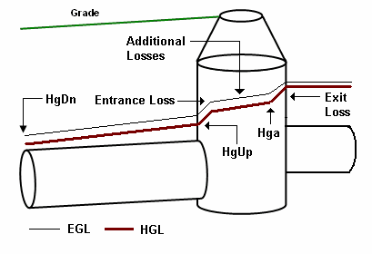
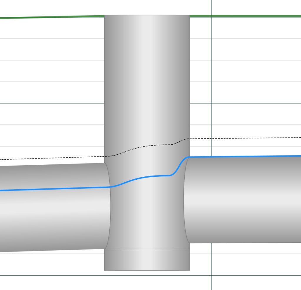
This method follows three fundamental steps and computes energy losses in each step.
Step 1. Entrance Loss
Determines an initial energy level based on either inlet control (weir and orifice) or outlet control (partial and full flow) equations.
Step 2. Additional Losses
This step makes adjustments to the energy level computed in Step 1. These adjustments are based on benching, angles of incoming lines, and plunging flows.
It is important to mention that these modifications can have either a positive or negative impact. For instance, benching typically minimizes energy losses, resulting in a potential decrease in the EGL line at the junction. Regardless, the adjusted energy level must not fall below the initial energy level calculated in Step 1.
Step 3. Exit Loss
An exit loss is computed from each inflow pipe and is added to the adjusted EGL in Step 2. This newly computed energy level is used as the starting energy (EGL) for the incoming line(s).
AASHTO Junction Loss Method
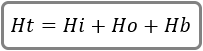
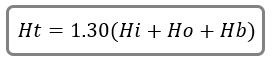
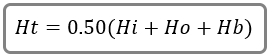
Similar to HEC-22, AASHTO junction losses are the sum total of entrance, additional losses, i.e., inflow bends and adjustments from plunging and shaping, and exit losses. The total junction, without adjustments, is computed with the following equation:
Where:
Ht = Total energy loss, ft
Hi = Entrance (expansion) loss, ft
Ho = Exit loss (contraction) loss, ft
Hb = Bend loss, ft
In addition, Ht will be adjusted for plunging flows as well as benching or inlet shaping. Each of these components are discussed in detail below.
Entrance (Expansion) Losses
These are looses that occur when the incoming flow expands into the structure are is computed using the following equation:

Where:
Hi = Entrance loss, ft
Ke = 0.35
Vi = Velocity in ft/s of incoming Line. Where more than one Line is present, the one with the greatest momentum (QxV) is used.
g = Gravity, 32.2 ft/s (9.8)
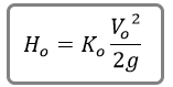
Exit (Contraction) Losses
Exit losses occur when the velocity changes as the flow contracts into the outgoing pipe. These losses are computed using the following equation:
Where:
Ho = Exit loss, ft
Ko = 0.25 (0.30 for initial inlets with no incoming Lines, or headwalls.)
Vi = Velocity in ft/s of outgoing Line.
g = Gravity, 32.2 ft/s (9.8)
Bend Losses
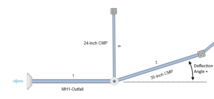
Bend losses are applied when one or more pipes enter a junction at deflection angles greater than zero. When more than one Line enters a junction at an angle, bend losses are computed for each one and the largest loss is used. Bend losses are computed as:
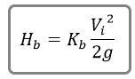
Where:
Hb = Bend loss, ft
Kb = Varies with the bend angle. See table.
Vi = Velocity in ft/s (m/s) of incoming Line
g = Gravity, 32.2 ft/s (9.8)
| Deflection Angle, deg | Kb | Deflection Angle, deg | Kb |
|---|---|---|---|
| 5 | 0.06 | 40 | 0.43 |
| 10 | 0.13 | 50 | 0.50 |
| 15 | 0.19 | 60 | 0.56 |
| 20 | 0.25 | 70 | 0.61 |
| 25 | 0.30 | 80 | 0.66 |
| 30 | 0.35 | 90 | 0.70 |
Plunging Losses
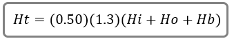
Applied when the captured inlet inflow is at least 20 percent of the total flow through the junction; or a lateral Line enters the junction with its invert above the crown of the exiting Line and its flow is at least 20 percent of the total. Plunging losses increase the total junction loss, Ht, by 30 percent.
Inlet Shaping, Benching
Refers to how the invert of the structure is shaped and can reduce the total junction losses by 50 percent.
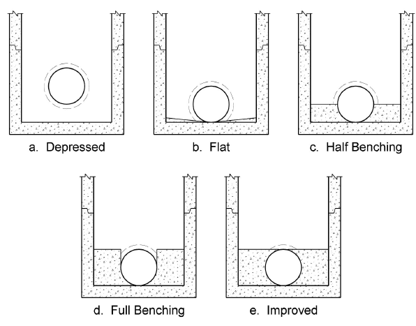
Structures that provide Half Benching, Full Benching or Improved qualify for a reduction as follows:
Where NO plunging losses occur:
Where plunging losses occur:
Bend Losses at None Junction Types
If Suppress Junction Losses has not been selected, bend losses will also be computed at junctions using a “None” junction type. Typically junctions using the “None” type will be disregarded regardless whether HEC-22 or AASHTO has been selected. However, bend losses will be accounted for.

Bend losses are calculated by the following equation per HEC-22:

Where:
Hb = Energy loss in ft (m)
Theta is the bend angle, or Deflection Angle in degrees of the upstream line
V = Velocity in ft/s (m/s) of incoming Line
Want to learn more? See, Water Surface Profiles for Storm Sewers in Further Reading for an in-depth article on this topic.