Typically, in the design of multi-stage outlets for detention ponds, a separate device is required for each frequency being modeled. For instance, a 2, 10, and 100-year model would typically involve a culvert, orifice, and either a secondary weir or a restrictor plate on the culvert. Although it is feasible to use fewer devices to accommodate all frequencies, it is not very likely. The resulting outlet structure will usually look something like this:
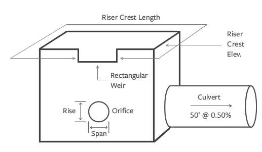
This is known as a “Multi-Stage” structure. Multi-Stage refers to the multiple stages or depths in the pond that this structure must address. In our case depths corresponding to the 2, 10, and 100 year runoff events.
You typically see as many devices in a multi-stage outlet structure as there events. In the figure above there are three. An Orifice, a Rectangular Weir and a Culvert. As for the Riser, well, it’s just there to contain the Orifice and Rectangular Weir while conveying their flows to the Culvert.
Since this article is more about the outlet structure design “procedure”, it won’t go into detail about the storage part or the actual storage-indication method calculations (See Further Reading below). But it’s important that you get this first step right. Ninety-nine percent of pond design failures are due to not having enough storage.
So let’s assume you already have done the storage estimating by developing the pre- and post-developed hydrographs. Be conservative, you can always scale the pond size back. It always helps to get a solution on your first trial pond routing.
So Where Does One Begin?
When sizing multiple outflow devices, it may seem logical to begin with the orifice, followed by the secondary weir, then the riser, and finally the culvert. This order aligns with designing based on return periods, such as 2-year, 10-year, and 100-year events. However, it is not advisable to follow this intuitive approach as it can consume a significant amount of time. The size of one device impacts the performance of others, creating a chain reaction.
A Step-by-Step Guide to Detention Pond Outlet Structure Design
Here’s the secret to a no-fail pond outlet structure design:
Design your devices starting downstream and work your way upstream.
1. Always start a pond design from the downstream end, working upstream. Avoid basing your work on frequency; instead, introduce structures starting from the downstream end and moving upstream. Add the Culvert first.
2. Size the Culvert to meet or exceed the highest of the Target Qs. If the closest culvert size far exceeds the target Q, it usually does, then you should plan on using secondary structures such as a weir or an orifice to satisfy this upper end. Perform a trial route to confirm. Use standard, commercially available sizes.
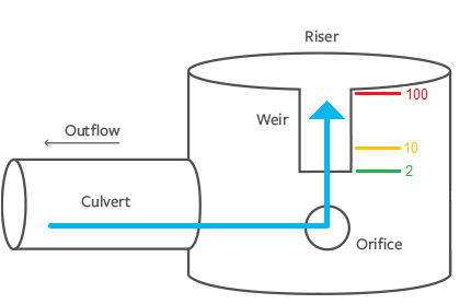
3. Next, add devices such as an orifice to satisfy the lowest Target Q. Perform trial routes using different orifice sizes to meet the Target Q. Use the maximum elevation reached in that routing to set the invert for the next upstream structure. For example, the trial routing below shows a Max Elevation of 103.90 at the 2-year where an orifice was added. Use this elevation to set the invert for the 10-year device.

You can add a Riser at this point to satisfy the visuals. Just be sure to set its crest elevation above the maximum elevation reached during the Trial Routing in the previous step where you added the Culvert. You can adjust this later.
4. Next, add a secondary weir or a second orifice to satisfy the intermediate frequency(s). Perform trial routes to determine the maximum elevation reached. Use this maximum elevation as the invert elevation for the next structure. Repeat this step for each intermediate frequency Target Qs. Experiment with v-notch as well as rectangular weirs. We have found more success with rectangular weirs however.

As shown above, the invert set for the rectangular weir (10-year) is set to 103.90, which matches the Max Elevation reached from the 2-year routing.
5. Finally, if you haven’t already done so, add a Riser structure to contain the multi-stage devices. Note that it is not recommended to use a Riser as a controlling device but in some cases this will be the most economical design. First try to use it simply as a container for other devices such as orifices and weirs. Set the Riser crest elevation to just above the maximum elevation reached in Step 4.
You could have added the Riser directly after adding the Culvert, but we did not know where to set its Crest elevation. In this case we could have guessed but set it high so that it would not affect outflows.
Add any necessary emergency spillway weirs. These are not multi-stage.
Further Reading
You can view this entire process in the following article:
My First Pre/Post Development Project – A step-by-step example of deigning a detention pond using the NRCS method.
Hydrology Studio has developed two sophisticated procedures for designing your outlet structures. They both use the Trial Route functionality. The First method utilizes the Schematic Chart while the second uses primarily the Stage-Discharge Curve.
- Design Using the Schematic – This approach allows you to setup the outlet structure right on the Schematic chart. This is a step-by-step example problem using this procedure applied to the Modified Rational method.
- Design Using the Stage-Discharge Curve – This approach, while not as real-life visual as the Schematic method, is just as effective and fast.