Culverts flow under two regimes:
- Outlet Control
- Inlet Control
Inlet control implies that it is more difficult for water to get in the pipe than it is to get through it. During outlet control, it is more difficult for flow to get through the barrel than it is getting inside of the barrel.
Outlet Control
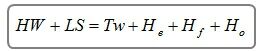
Outlet control flow conditions are calculated based on energy balance.

The total energy required to pass the flow through the culvert barrel is the sum of the entrance loss (He), the friction losses through the barrel (Hf), and the exit loss (Ho).
Exit Loss
The exit loss is computed by the following equation:
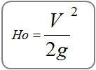
Where:
V = velocity exiting the culvert in ft/s (m/s)
g = acceleration due to gravity
Friction Loss
Culvert Studio uses the energy-based Standard Step method when computing the friction loss. This methodology is an iterative procedure that applies Bernoulli’s energy equation between the downstream and upstream ends of the culvert. It uses Manning’s equation to determine head losses due to pipe friction.
This method makes no assumptions as to the depth of flow and is only accepted when the energy equation has balanced.
The following equation is used for all flow conditions:
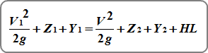
Where:
V = velocity in ft/s (m/s)
Z = invert elevation in ft (m)
Y = HGL minus the invert elevation in ft (m)
HL = energy head loss due to friction
Friction losses are computed by:
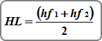
Where:
HL = energy head loss due to friction
hf1 = friction head at the downstream end
hf2 = friction head at the upstream end
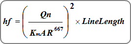
Where:
Km = 1.486 (1.0)
n = Manning’s n
A = cross-sectional area of flow in sqft (sqm)
R = hydraulic radius
Composite n-values
Culvert Studio uses the Horton-Einstein equation to compute a composite n-value for open-bottom arch sections.
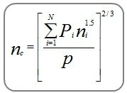
Where:
nc = composite n-value
Pi = wetted perimeter of subdivision i
ni = n-value for subdivision i
p = total wetted perimeter
Entrance Loss
The entrance loss is a function of the velocity head in the barrel, and is expressed as a coefficient times the velocity head.
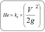
Where:
V = velocity exiting the culvert in ft/s (m/s)
g = acceleration due to gravity
Ke = coefficient based on inlet configuration per HDS-5. See table below.
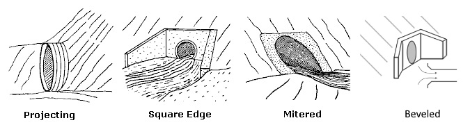
| Inlet Configuration | Entrance Loss Coefficient, Ke | |||
| Circular | Arch | Rectangular | Elliptical | |
| Projecting | 0.5 | 0.9 | 0.5 | 0.5 |
| Square Edge | 0.5 | 0.5 | 0.5 | 0.5 |
| Mitered | 0.7 | 0.7 | 0.7 | 0.7 |
| Beveled | 0.2 | 0.2 | 0.2 | 0.2 |
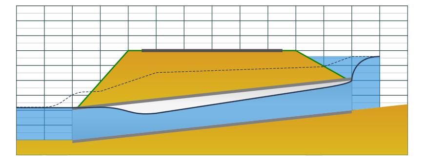
Inlet Control
Inlet control occurs when it is harder for the flow to get through the entrance of the pipe than the remainder of the pipe barrel.
The figure below illustrates inlet control flow. The control section is at the upstream, inlet end of the culvert. Depending on the tailwater, a hydraulic jump may occur downstream of the inlet.
The following inlet control equations are used. If Hw (the upstream water surface elevation) is above the pipe crown the Submerged equation is used. Otherwise the Unsubmerged equation is used.
Submerged
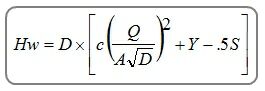
Unsubmerged
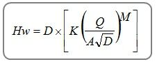
Where:
Hw = headwater depth above invert
D = culvert Rise in ft (m)
Q = flow rate in cfs (cm/s)
A = full cross-sectional area of pipe in sqft (sqm)
K, M, c, Y = coefficients based on inlet edge configurations
S = culvert slope, ft/ft (m/m)