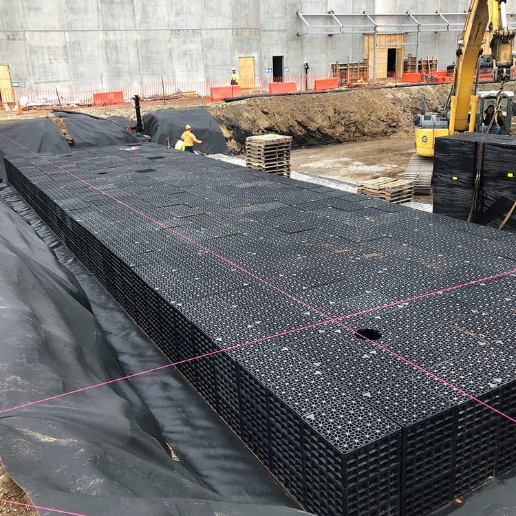
This article illustrates how to establish your pond utilizing the R-Tank® stormwater modules from Ferguson Waterworks, or any other modular-type tank. The focus on these types of tanks is significant as they differ from the “Manufactured” format for underground chambers in Hydrology Studio, primarily because they lack the conventional stone encasements employed therein, and with so many models to choose from, can be arranged in countless configurations.
UPDATE: The R-Tank MD Single (1), Double (2), Triple (3) & Quad ( 4) are now included in the “By Manufacturer” list as a built-in UG Chamber. If you are needing to design for the R-Tank HD, SD or UD, please follow the guidlines in the remainder of this article.
Example
This example design aims to implement a shallow subsurface stormwater management system located beneath a small parking area. It is projected that 10 rows consisting of 27 modules, amounting to a total of 270, will be necessary. In conjunction with the loading specifications, this necessitates the use of the R-Tank UD Triple (3) module, which features a 95 percent void ratio.
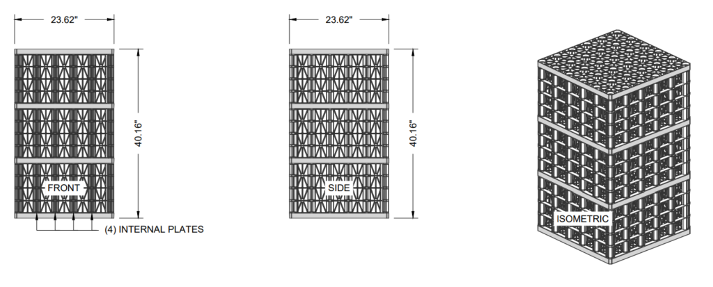
Dimensions
Width = 23.62″ or 1.97 ft
Length = 23.62″ or 1.97 ft
Height = 40.16″ or 3.35 ft
Storage
Gross Volume = 12.97 cuft
Net Volume after 95% Void = 12.35 cuft
Total Available Storage = 270 x 12.35 = 3,335 cuft
There are two ways you can model R-Tank modules in Hydrology Studio. Using the Generic UG Chamber option or as a Trapezoid. Both options will be illustrated below.
As Generic UG Chambers
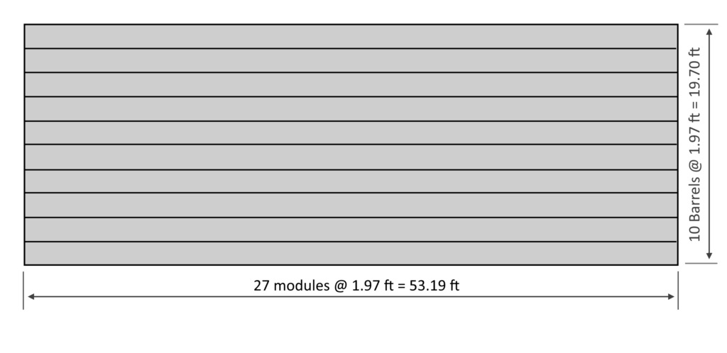
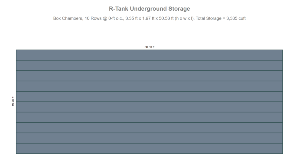
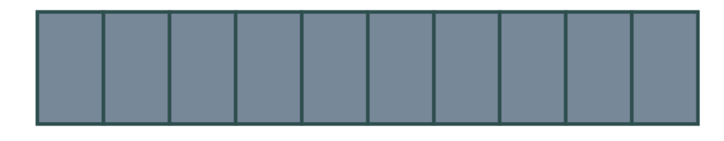
The proposed layout shown above consists of 10 rows (barrels), each containing 27 modules in length. Generic UG Chambers do not provide a voids input for the chambers themselves so it is important to adjust the Barrel “Length” input to reflect the decrease in gross volume caused by the 95 percent voids in the modules. Therefore, we will calculate the adjusted length as 53.19 x 0.95, resulting in 50.53 ft.
To begin, open the Pond Designer and go to Step 2 – Create Pond. Enter a pond name, for example, R-Tank. Then select UG Chambers as the pond type. Enter the following data.
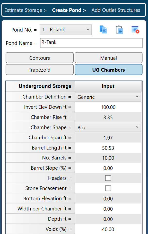
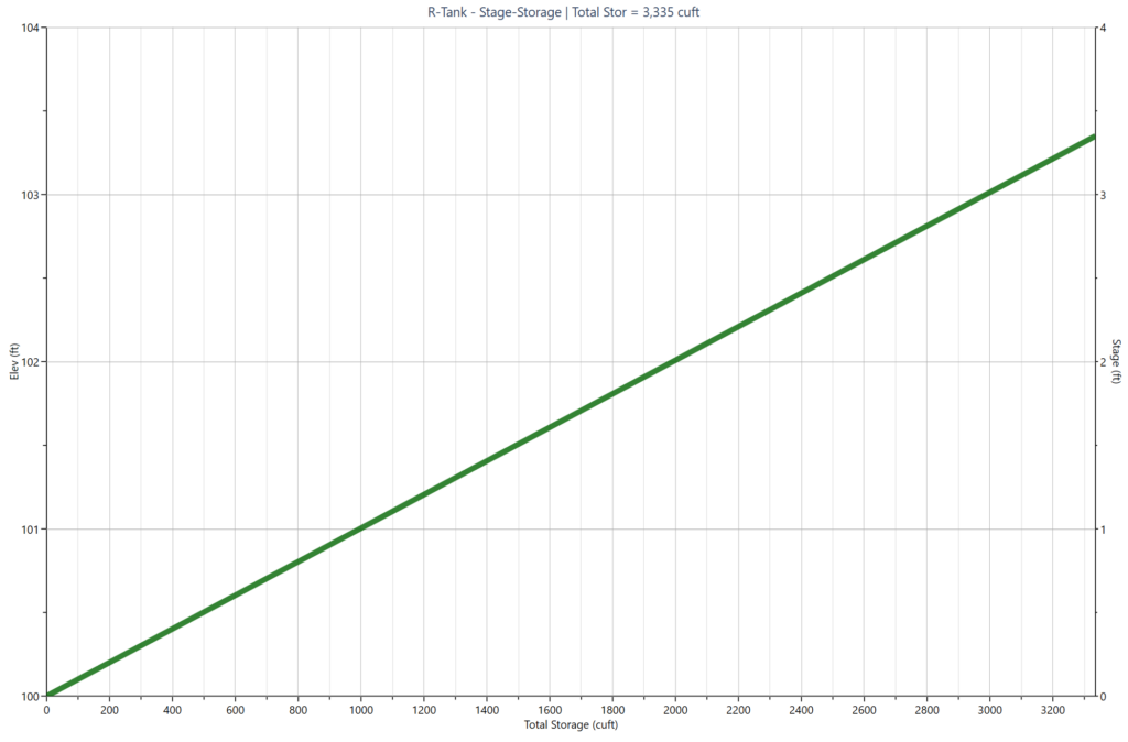
Be sure to click [Apply] when done. Then select “Layout Chart” to render the following Plan indicating Total Storage of 3,335 cuft. The Section and resulting Stage-Storage curve are shown below.
To efficiently configure your UG Chambers with R-Tank Stormwater Modules as Generic Chambers, only four inputs are necessary. Ensure that you modify the Barrel Length input according to the recommended percent void for the module, which is 0.95 in this instance. You also have the option to decrease the Chamber Span.
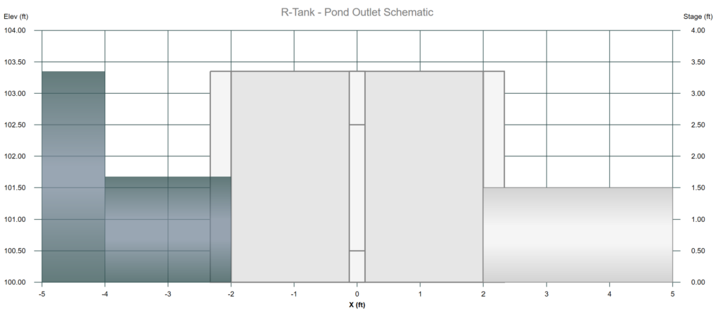
Add the Outlet Structure
You are now prepared to incorporate the outlet structure. Hydrology Studio offers a straightforward and efficient method for specifying outlet devices for underground detention chambers. Once the chambers are designated as a storage type (either Generic or By Manufacturer), the software automatically generates a specialized outlet structure box, akin to a Riser, allowing you to include an outflow culvert, weir wall, and orifice. Please visit this page for complete details.
Irregular Shaped Plan Layouts
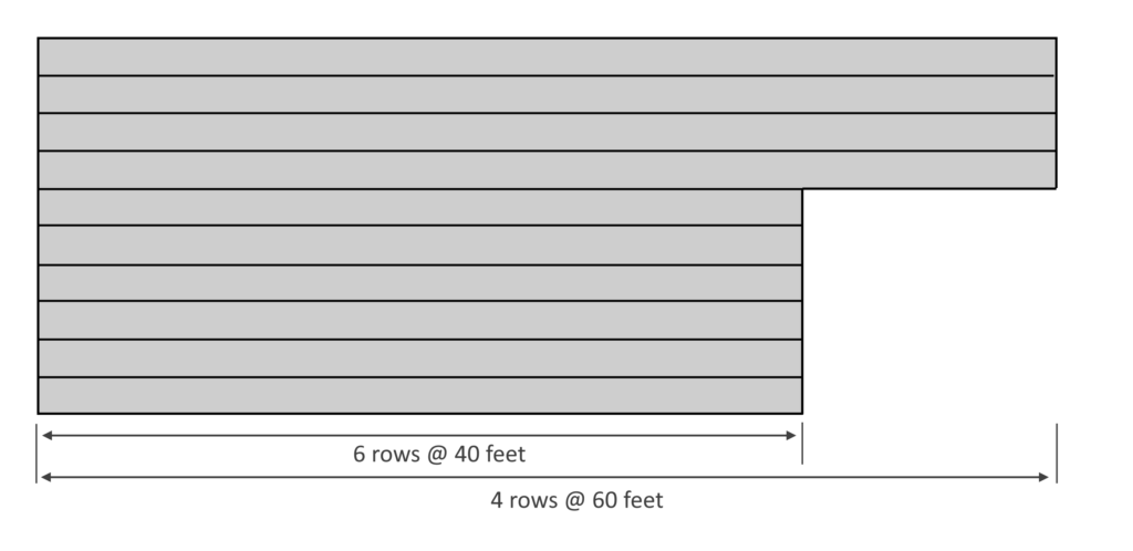
There may be instances where site limitations hinder the implementation of a straightforward rectangular layout as outlined. Specifically, you might face multiple rows featuring different barrel lengths. In such cases, calculate the total of the barrel lengths and divide this sum by the number of barrels or rows to determine the average. Input this average value for the Barrel Length in the software.
In the example plan below, the total length would be 6 x 40 + 4 x 60 = 240 + 240 = 480 feet. The average barrel length is 480/10 rows = 48 feet. Multiply that by 0.95 to adjust for the module void or 48 x 0.95 = 45.60 feet. Enter 10 Barrels and 45.60 for the Barrel Length.
Please remember the installed length should be based on the actual chamber dimensions, not the voids-adjusted dimension.
As a Trapezoid
Alternatively, you may opt for the Trapezoidal-shaped pond. It offers the same level of simplicity as the Generic UG Chambers and includes a Voids input so you will not need to make any dimension adjustments. To configure the Trapezoid, simply input the plan’s Width, Length, Depth and Voids.
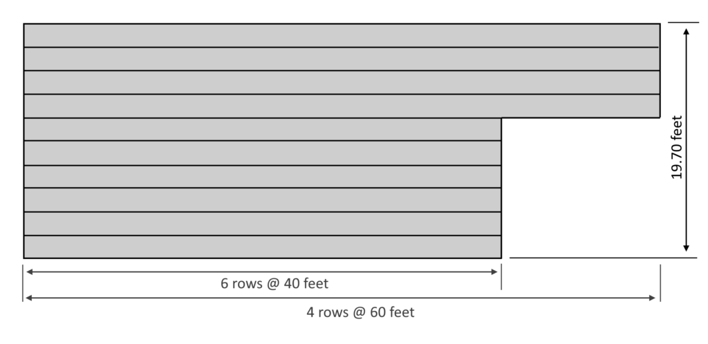
This plan has a Width, Length and Height of 19.70, 53.19 and 3.35 respectively.
To begin, open the Pond Designer and go to Step 2 – Create Pond. Enter a pond name, for example, R-Tank. Then select Trapezoid as the pond type. Enter the following data.
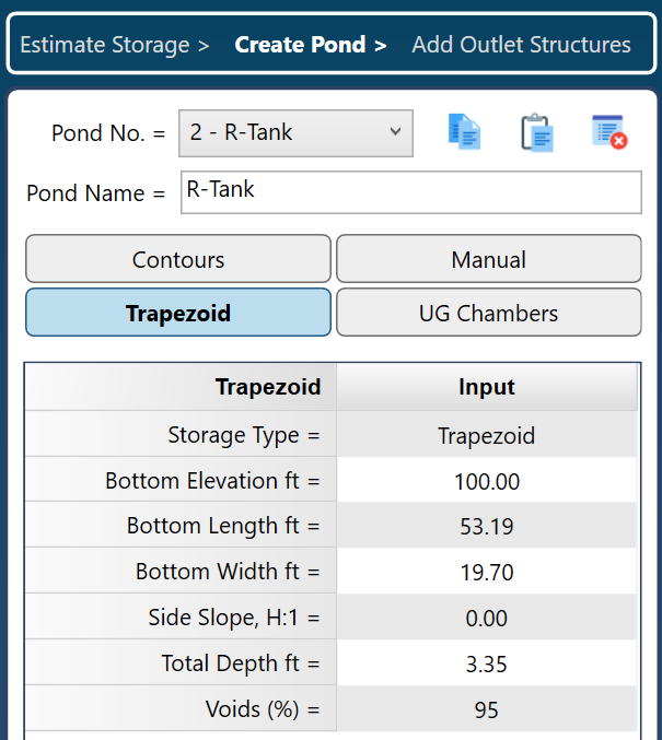
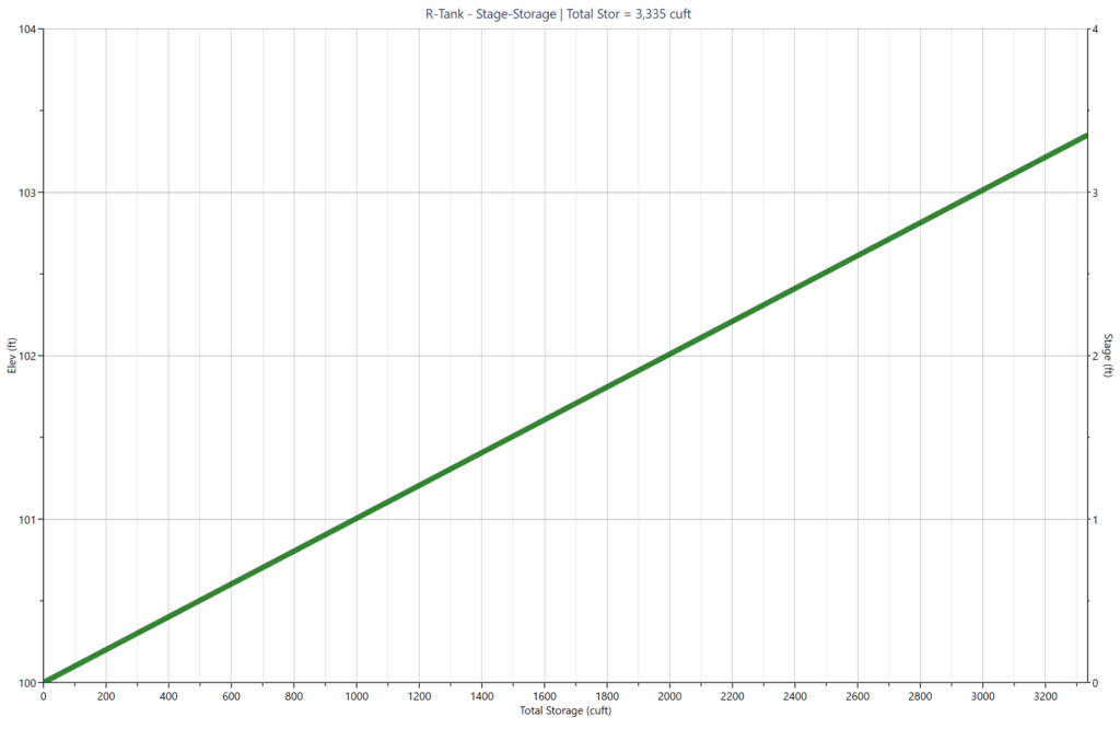
Be sure to click [Apply] when done. Then select “Stage-Storage” to view the following Stage-Storage curve indicating Total Storage of 3,335 cuft. Identical to the Generic UG Chambers inputs.
Irregular Shaped Plan Layouts
There may be instances where site limitations hinder the implementation of a straightforward rectangular layout as outlined. This means you could have several rows featuring different barrel lengths. In such cases, calculate the total of the barrel lengths and then divide that sum by the number of barrels or rows to determine the average. Input this average value for the Bottom Length in the software.
In the example plan below, the total length would be 6 x 40 + 4 x 60 = 240 + 240 = 480 feet. The average barrel length is 480/10 rows = 48 feet. Enter 48 for the Bottom Length and 19.70 for the Bottom Width. The objective is to input various combinations of Bottom Length and Width to achieve the total surface area specified in the layout plan.
Add the Outlet Structure
You are now prepared to incorporate the outlet structure. When utilizing a trapezoidal shape, the software will not automatically include a riser structure, in contrast to the UG Chambers. Please visit this page for complete details.
Conclusion
It is our hope that this article has provided you with valuable insights and knowledge. When you come across UG Chambers that are not included in Hydrology Studio’s “by Manufacturer” list, please refer to one of the procedures described above.
Both approaches are easy to implement and require only four inputs. The Generic method involves adjusting either the length or width of the chamber to accommodate a void factor, and it also offers the benefit of a dedicated Riser outlet structure commonly associated with UG chambers. On the other hand, the Trapezoid method features straightforward inputs and includes a built-in voids input, although it requires that you add a conventional Riser structure.
As demonstrated, both methods yield the same Stage-Storage curve, ensuring that the results for routing an inflow hydrograph will be identical.