In addition to bridges and culverts, you can add an inline overflow weir to your models. The weir could represent an emergency spillway or a gated overflow.
Sharp or Broad Crested?
Channel Studio automatically determines the type of weir structure (sharp or broad crested) based on the depth of flow compared to the weir width and will apply the appropriate weir coefficient. If the weir width is less than one-half the depth of flow, it will be considered a sharp-crested weir. Otherwise, it’s a broad crested weir. The Quick Results table as well as the printed outputs will indicate which was used. Most weirs are broad crested.
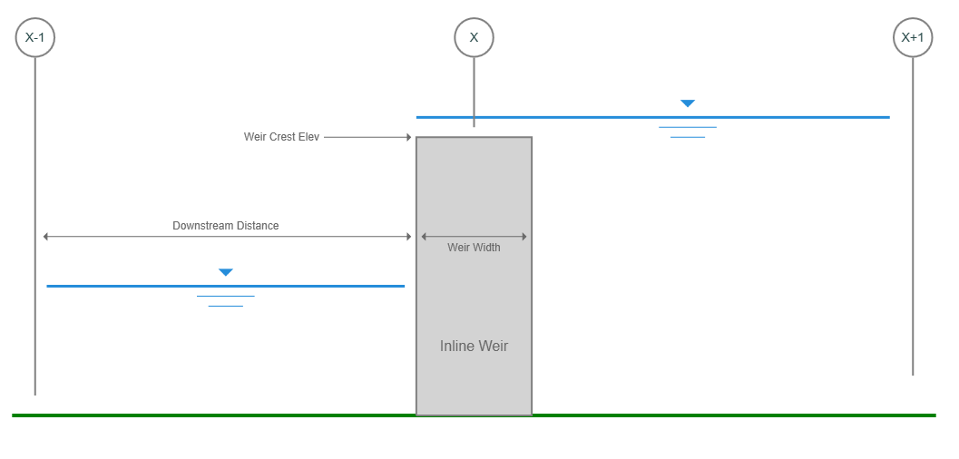
Like bridge and culvert sections, the weir section inherits the cross-section geometry of the section just downstream. The weir crest elevation is set by a single input and will stretch across the entire cross-section.
You can add weir sections to your model at any time. Just follow the same procedure as described in “Adding Cross-Sections”, except you’ll use the Weir section button.


Energy losses are computed in 3 parts:
- From the reach immediately downstream of the weir
- Through the weir structure itself
- To the reach immediately upstream of the weir
Locating Weir Sections
Each inline weir will need to have a Channel section located just downstream (a few feet or 1 meter) of the weir and one just upstream as shown below.
Procedure for Locating Inline Weirs
The best procedure for locating your weir and related cross-sections is to first determine the river stations of your sections. For example, given the following:
Inline weir is located at River Sta 4+00
Weir Length (parallel to the channel) = 4 ft.
Downstream Distance is 5 ft.
Reach Length for the upstream channel section is also 5 ft.
Here’s where to place Sections 2, 3 & 4 where 3 is the weir section:
Section 2
At the centerline of the weir minus one-half the weir length minus the distance to Section 2. Sta 400 – 4/2 – 5 = 3+93
Section 3
At Sta 4+00
Section 4
At the centerline of the weir plus one-half the weir length plus the distance to Section 4.
Sta 400 + 4/2 + 5 = 4+07
Now just add them to your model at these river stations. Remember, you can always adjust the locations and reach lengths at any time either via the Model or by direct entry of the section data.
When making adjustments to cross-section locations on the Model tab, Channel Studio will automatically set the reach lengths and downstream distances for you.