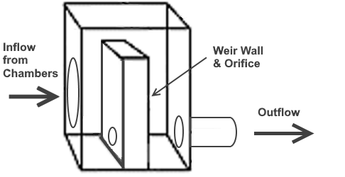
Hydrology Studio provides an easy and convenient way to define outlet devices for underground detention chambers. When chambers have been defined as a storage type in Step 2, (Generic or By Manufacturer) the software automatically inserts a special outlet structure box (similar to a Riser) for which you can add an outflow culvert, orifice and weir as shown in the typical structure below.
The schematic structure (Riser) is assumed to be a 4 ft x 4 ft rectangle. Its width will automatically expand larger if needed to accommodate larger devices. The depth will remain at 4 ft. Of course this is purely for schematic purposes. Final constructed dimensions are the responsibility of the designer.
Adding Outlet Devices
Initially the Riser structure will be empty. Again, the software automatically adds a Riser structure when using UG Chambers so do not add one. You will only add a Culvert, Orifice, Weir, Exfiltration, etc., the same way as described in Step 3 – Add Outlets.
All outlet devices are optional. For example, you can add just a single orifice, a single weir, culvert, or any combination. Just be sure to mark your secondary structures (orifices and weirs) as “Multi-stage” or “Flows through Culvert” if you are employing an outflow culvert.

The Schematic above shows the outlet structure with a Rectangular Weir, Orifice, Culvert and Exfiltration in a frontal view. The structure which contains these devices was added by the software automatically.
Click the Side link at the bottom of the schematic drawing to view a side section as shown below.

In the structure above, both Orifice and Weir must be checked as “Flows through Culvert” as they flow through the Culvert. The inflow pipe from the Chambers has been arbitrarily sized and is assumed to have no effect on the hydraulics. Be sure to size this pipe large enough in the field so that it will not attenuate flows to the outlet structure. The Weir crest elevation should be set high enough to maximize the storage of the chambers but not at or above the Top of Stone, shown as the heavy gray line.
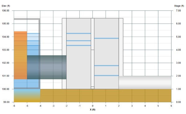
This is the same structure after performing a Trial Route. The Struct HG check box has been checked to show the water surface on both sides of the Weir Wall. Note the elevations of the water surface in the chambers where the storage has been fully utilized. The maximum water surface is also allowed to rise into the stone layer above.
Tips for Underground Detention Ponds
Generally when designing outlets for detention ponds, you’ll need a device for each frequency you wish to model. For example, a 2, 10 and 100 year model will most likely need a culvert, orifice and either a secondary weir or a restrictor plate on the culvert. While it is possible to satisfy all frequencies with fewer devices, it’s not very probable… except when dealing with underground storage. In many cases we have been able to satisfy all release rate requirements with a single outlet pipe or culvert.
- When setting up your chambers, add a little more than you think you’ll need. The maximum head you’re dealing with is much lower than working with traditional above-ground ponds which constrains outflow potential. This often times leads to needing more storage than anticipated. Once you have performed a few Trial Routings, you can return to Step 2 and adjust (up or down) the number of chambers as needed. The goal is to maximize the depth in the chamber system so that it’s full storage potential is realized.
- Add the Culvert first. If you know you’re going to utilize a culvert, add it first. It is best to start your outlet selection from the downstream end, working upstream. Ideally it is this device that will control the final outflow. Size the Culvert to meet or exceed the upper end of the Target Curve. It cannot be below the target Q. If the culvert outflow far exceeds the target Q, then you should plan on using secondary structures to satisfy this upper end. A restrictor plate over the Culvert is a popular method. Perform a trial route to confirm. Use standard, commercially available sizes.
- Add a secondary rectangular weir or another orifice to satisfy the intermediate frequency(s). Perform trial routes to determine the maximum elevation reached. Use this elevation as the invert for the next upstream structure. Repeat this step for each intermediate frequency. Rectangular weirs seem to work the best.