
Channel Studio is capable of modeling culverts with various slopes, lengths, sizes, materials and shapes including circular, rectangular, arch and open-bottom arch. It also handles a variety of culvert materials and inlet configurations.
Any cross-section can be a Culvert except Section Number 1 or the very last section. You can add culvert sections to your model at any time. Just follow the same procedure as described in Adding Cross-Sections, except you’ll use the Bridge/Culvert section button and select “Add Culvert Section” from the pop-up menu.

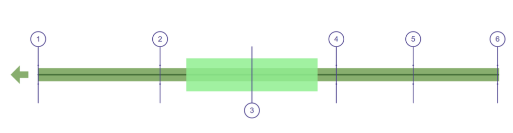
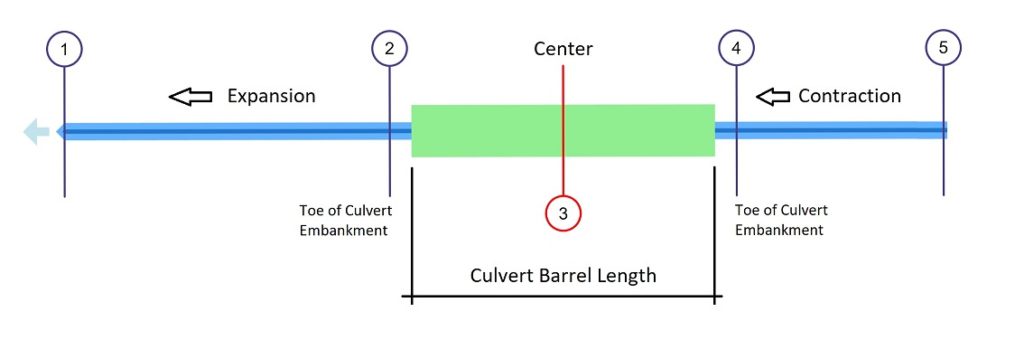
Section 3 above is a newly added Culvert Section. Below is the same plan after data was added.
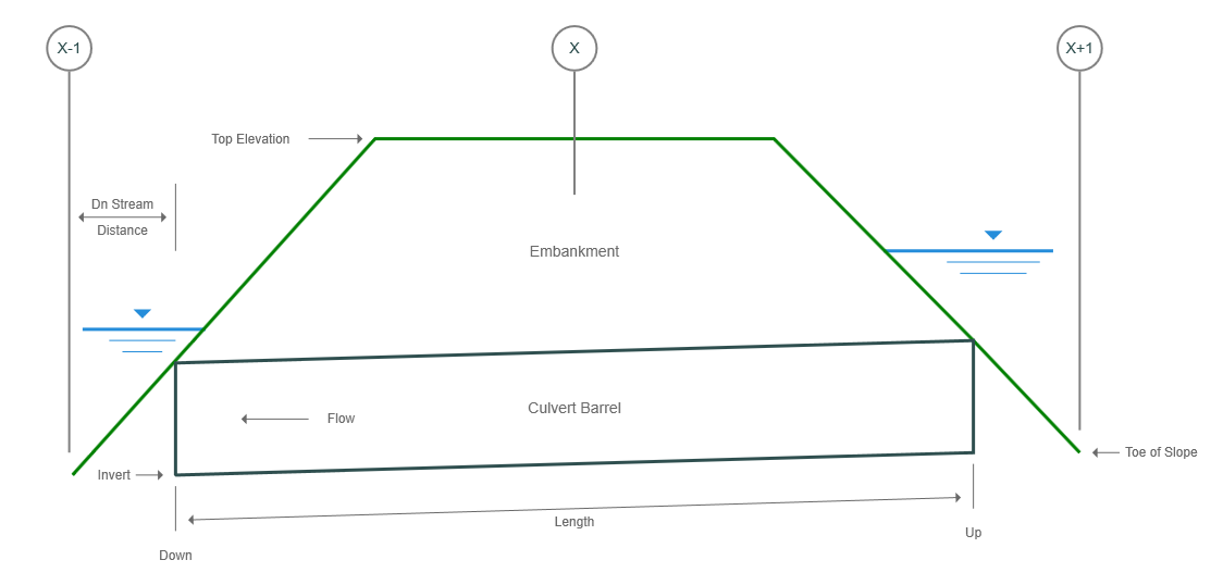
Typical Culvert cross-section below.
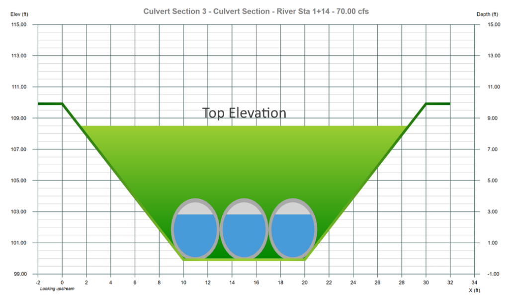
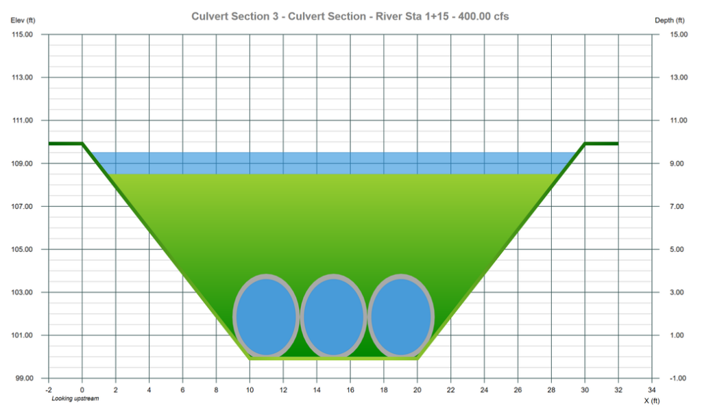
It is not necessary to specify geometric data for the Culvert cross-section as it automatically inherits that from the next downstream section. Note however, that the Top Elevation must be below the highest point in the Section data. It is this top elevation, or roadway, that will serve as an overflow spillway if the water surface exceeds it as depicted below.
Above is an example plan view of a culvert with flow paths. This culvert is 70 feet in length. Section 2 is 15 feet downstream from the ends of the culvert. Section 4 is 10 feet upstream from the culvert entrance. Section 2 is located at River Sta 65. Section 3 at 115 (65 + 15 + 70/2) and Section 4 is at 160 or 115 + 70/2 + 10.
Locating Culvert Sections
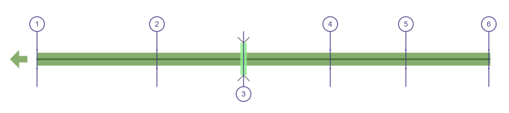
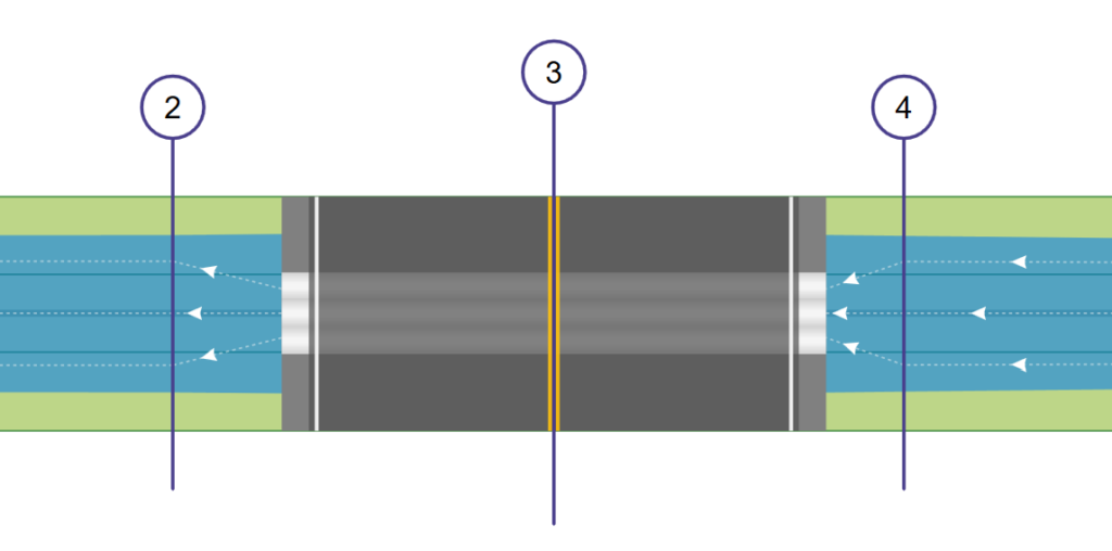
Each culvert crossing will need to have a Channel section located just downstream of the culvert, typically about 5 to 15 feet (2 to 5m) and one just upstream, also about 5 to 15 feet, as shown below. These sections should be located at the toe of the culvert embankment and represent the natural channel adjacent to the culvert.
The Section at X-1 below is located at the “Downstream Distance” described above.
In addition, a proper model will also include those sections sufficiently downstream and upstream (Sections 1 & 5 in the figure below) to where the flow has fully expanded and is not affected by the structure. These sections become less important as the embankment side restrictions lessen.
Procedure for Locating a Culvert
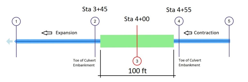
The best procedure for locating your culvert and related cross-sections is to first determine the river stations of your sections. Then add those sections to your reach. For example, in the plan above and given the following:
Culvert is located at River Sta 4+00 (randomly chosen for this example).
Culvert Barrel Length = 100 ft.
Downstream Distance is 5 ft.
Reach Length for the upstream channel section is also 5 ft.
Here’s where to place Sections 2, 3 & 4 where 3 is the actual Culvert section:
Section 2
At the center of the culvert barrel minus one-half the culvert barrel length minus the downstream distance to Section 2. Sta 400 – 100/2 – 5 = Sta 3+45
Section 3 (the actual Culvert section is at its centerline)
At Sta 4+00
Section 4
At the center of the culvert barrel plus one-half the culvert length plus the distance to Section 4. Sta 400 + 100/2 + 5 = Sta 4+55
Add these Sections to your model at these river stations. Remember, you can always adjust the locations and reach lengths at any time either via the Model or by direct entry of the section data’s River Station.
When making adjustments to to section locations on the Model tab, Channel Studio will automatically set the reach lengths and downstream distances for you.