
Culvert sections are added just like any other channel section. Just click on the Bridge/Culvert Section button on the side tool bar on the Model tab and choose “Add Culvert Section”. Move your mouse to the desired river station and click your mouse. Then click the [Ok/Select] button or press escape when finished.
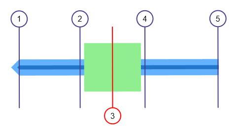
A typical model layout containing a culvert at Section 3 will look like this:
Culvert Section Data
It’s important to note that bridge or culvert sections do not require geometric (Station, Elevation) data. Rather they inherit the data from the previous downstream section. For example, in the model shown above, Culvert Section 3’s geometric data will be bound to Section 2.
Then all that’s needed are inputs pertinent to the structure itself which are described below.
The input requirements are designed to be minimal but thorough. To enter data, type in the value or select from a drop-down input box, and press [Enter] or the [Tab] key.
Data is divided into three categories. Reach Length, Embankment and Culvert. While entering data for the first time, the canvas will automatically display help diagrams to assist in your data entry.
Name
Optional but it is a recommended input.
Downstream Distance
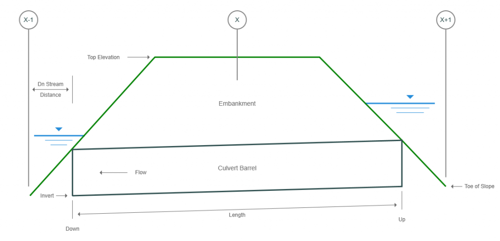
Enter the distance from the downstream channel section to the downstream edge of the culvert. Keep this short. Usually around 5 feet (2m). This is the distance from the toe of the culvert embankment to the edge of the culvert barrel and represents the natural channel adjacent to the culvert.
Embankment
Length
Enter the length of the culvert pipe. The length for pipes with mitered inlets is measured along the top or crown of the pipe.
Top Elevation
Enter the elevation of the top of the embankment. This elevation will be used to trigger overtopping (weir) flow. The distance between where the embankment intersects the channel banks is what is used as the weir crest length during weir flow calculations.
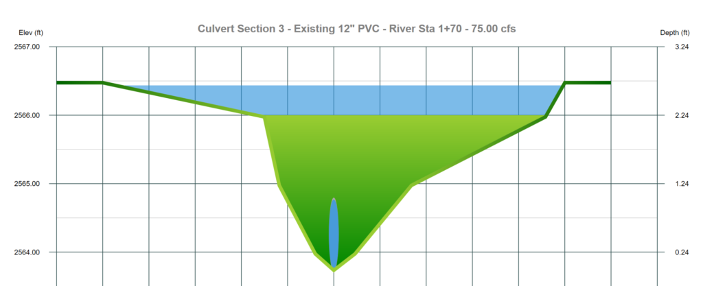
Be sure to specify a Top Elevation below the highest elevations in the channel as shown below. This insures the flow will be contained.
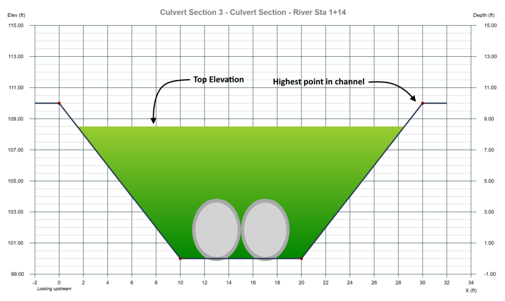
For example, the coss-section data below can contain overtopping flow.
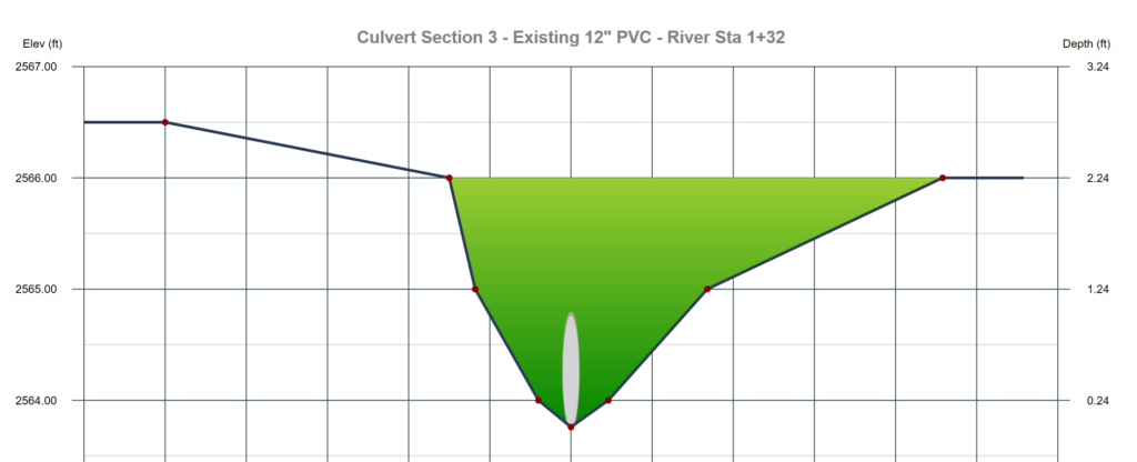
The section below will not contain any overtopping flow.
Culvert
Shape
Select the barrel shape from the drop-down list box.
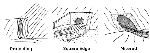
Inlet Configuration
Select an inlet edge from the drop-down list box.
Material
Select the barrel material from the drop-down list box.
Note: The culvert’s roughness coefficient is based on this input. The n-values used can be viewed/edited in the Project Settings.
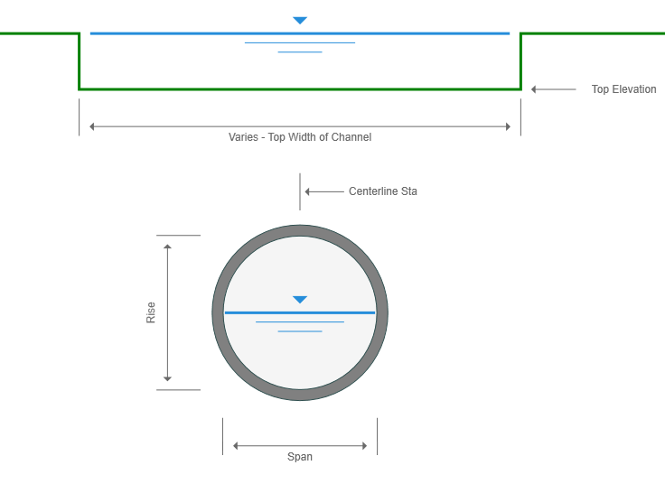
Rise
Enter the height of the barrel in ft. (m).
Span
Enter the width of the barrel. Circular sections will always have equal Rise and Spans.
Invert Elevation Down
Enter the invert elevation for the downstream end of the culvert.
Invert Elevation Up
Enter the invert elevation for the upstream end of the culvert.
Number of Barrels
Enter the total number of identical barrels. Six is the maximum allowed and they are each assumed to be at the same elevation and slope.
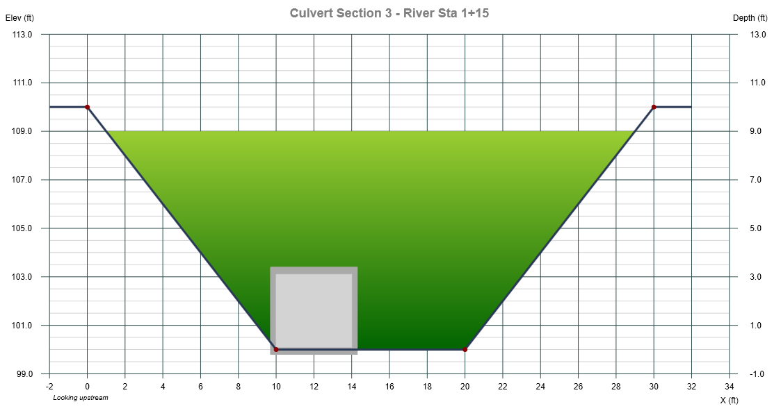
Centerline Station
Cosmetic only. This sets the horizontal location of the culvert barrel(s). For example, in the section shown below, the centerline of the barrel is set to 12 ft. To move the barrel to the center of the channel, you would set the Centerline Station to 15 ft.
Apply Your Data
To accept your inputs, click [Apply]. Channel Studio will immediately setup ineffective flow areas for the downstream and upstream sections.