Studio Express has the ability to analyze up to ten inlets of the following types:
Curb
Grate
Combination
Drop Curb
Drop Grate
Inlets can be located in a sag or on a longitudinal slope and can be of any size. The purpose of this analysis is to determine the amount of flow a particular inlet can capture, the ponding depth, inlet and gutter spread widths, and the amount of flow that is bypassed. Results include cross-section plots and rating curves.
Methodology
Studio Express follows the methodology of FHWA HEC-22 for inlet interception capacity calculations.
Inlet & Gutter Spreads
In short, spreads are reported at both the face of the inlet and just upstream of the inlet. When an inlet is in a Sag condition, the spreads are the same and are determined by the depth (water surface elevation) at the inlet face. This elevation is simply projected across the Sx and Sw cross-slopes to determine the spread.
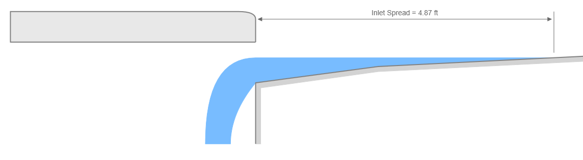
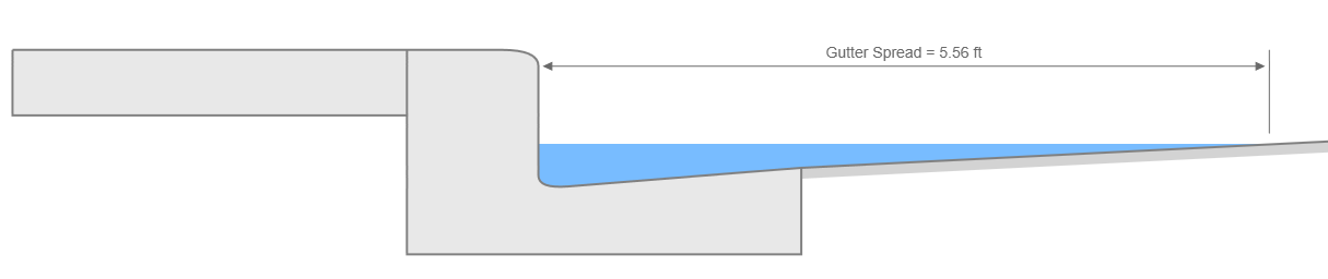
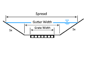
When On Grade, as shown in the two cross-sections below, the two spreads can be different but keep in mind that spreads are typically higher upstream of the inlet face and the gutter properties, Sx, Sw and Longitudinal Slope have the most influence on the spread widths. Not so much the inlet itself. The inlet is designed to capture flows and remove them from the gutter, but can do little to manage spread widths upstream.
Common Inlet Data
Regardless of which type of inlet you use, they will each have four common data items plus the discharge data described further down.
Inlet Id (optional but recommended)
Enter any name or label that you wish to help identify this inlet. For example, G7.
Inlet Type
Choose the type of inlet from the drop-down list box or select from the canvas. Each of these inlet types are described individually below in this article.

Location
Please choose this inlet’s location (On Grade or Sag) from the drop down list box. Note that inlets On Grade must specify the gutter’s longitudinal slope. If the inlet is in a Sag, then there will be no bypass flow. All of the flow will be captured. Inlets On Grade may or may not capture 100 percent of the flow.
Clogging Factors
Unique Clogging factors can be specified for inlets containing a curb opening or a grate, on grade or in a sag. These are entered as a percent.
Inlet Types
The remainder of this section provides descriptions of the required data for the types of inlets you can model.
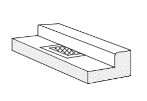
CURB INLET
Curb inlets are the workhorses of the industry. Pound-for-pound they are the most effective of all the street-type inlets and get a high rating for capture capacity. They are most effective in sags and when on grades of less than about 3%.
A typical curb opening inlet will have a rectangular opening along the face of the curb to which it is attached. Curb inlets can have Horizontal or 45-degree Inclined Throat openings. This data item is fixed for all inlets of this type in a given project and can be set in the Settings.


Total Inlet Length
Enter the total horizontal length of the opening.
Throat Height (Horizontal throat)
This is the height of the opening and is measured from the projection of cross slope, Sx. Do not include any local depression amount. See Gutters below for more information.
Throat Height (Inclined throat)
This is the height of the opening and is measured perpendicular to the throat opening angle (assumed to be 45-deg). Local depression not required.
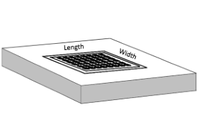
GRATE INLET

Grate inlets are deceiving in that they appear to be able to capture a lot of runoff because they are flush to the gutter. But in fact, they are the least effective among the street inlets.
When using these, don’t expect to get much runoff removal, especially when employed On Grade. The problem is that their capture capacity is dependent on the upstream spread widths which are typically substantially wider than the grate width. That portion of the spread that exceeds the grate width just passes on by, not giving the grate a chance to capture it. Clogging is a major issue with these as well.
Opening Area
Enter the clear opening area of the grate. Required only in sags.
Grate Width & Length
Enter the width and length of the grate.
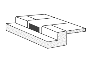
COMBINATION INLET
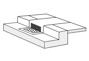
Combination inlets can capture up to 18% more flow than a stand-alone grate inlet, due to their ability to remove debris from the grate. Combination inlets require the same input data as both Curb and Grate Inlets. Combination inlets are assumed to have horizontal throat openings, no inclined throat.

Per HEC-22, the capacity of combination inlets on grade is equal to the grate alone and that the curb-opening is used to collect and remove debris. Capacity is computed by neglecting the curb opening.
Combination “Sweeper” Inlets
Note that you may enter unique lengths for the grate and curb opening. When the curb opening length is longer than the grate length, the program assumes the open curb portion to be located upstream of the grate, often called a “sweeper” inlet.
The sweeper inlet has an interception capacity equal to the sum of the curb opening upstream of the grate plus the grate capacity. The grate capacity of sweeper inlets is reduced by the interception of the upstream cub opening.
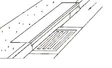
DROP CURB INLET
 Drop Curb inlets are a type of curb inlet used in sags in open yard areas. They typically have four sides with rectangular openings. Note that the length entered should be equal to the sum of the four clear-opened sides and that compound cross-slopes are not allowed, i.e. Sw is not a required input.
Drop Curb inlets are by far the most effective of all inlets. They borrow from their Curb Inlet cousin but have a much higher capture capacity due to their four sides. Plus, the cross-slopes can be greater because they are not constrained by typical street curb & gutter standards.
 Location
Drop Curb inlets are assumed to be in Sag locations.
Total Inlet Length
Enter the total length (all four sides or if circular, the total circumference) of the opening.
Throat Height
This is the height of the opening.
DROP GRATE INLET
Drop grate inlets can be in either sag or on-grade locations which means there can be bypass flows associated. These inlets are typically used in parking lots or open lawn spaces when in sag locations. Use in drainage swales, bar-ditches or v-shaped gutters in on-grade situations. Compound cross-slopes are not used, i.e. Sw is not a required input.
 Opening Area
Enter the clear opening area of the grate. Required only in sags.
Grate Width & Length
Enter the width and length of the grate. Must be <= Gutter Width.
Gutters
Among other data, each inlet has a gutter cross section that consists of a gutter width and slope, and compound gutter cross slopes, Sw and Sx, and an optional local depression, a. HEC-22 -type inlets can be very confusing and hopefully this article will help to simplify.

Sx
Sx is the cross-slope of the pavement section between the center of the pavement and the edge of the gutter. Common value is 2% or 0.02 feet per feet.
Sw
Sw refers to the cross-slope of the gutter section just upstream of the inlet opening. This is not necessarily the cross-slope of the gutter section at the face of the inlet. See Local Depression below. Common values of Sw hover around 5% or 0.05 feet per feet.
Local Depression, a
The local depression basically describes the gutter slope at the face of the inlet. But instead of describing it as a slope, it is described as the vertical distance between a projection of slope, Sx, and the invert of the inlet opening. Note the heavy dotted line in the sketch above. Typical values range from 1 to 3 inches.
Note that if Sw > Sx, then HEC-22 considers it to be a depressed inlet. Depressed inlets will have smaller spreads at the face of the inlet but has no affect on the computed spreads upstream in the gutter section.
Required Inputs
The following describes individual data items for inlets and gutters. Note that certain cells on the input grid will be marked out with “n/a“ or will not appear at all. This indicates that data is not required for that particular junction. Simply [Tab] through those cells.
Cross Slope, Sx
Enter the transverse slope of the pavement section only, Sx. See figure above.
Cross Slope, Sw
Enter the transverse slope of the gutter section only, Sw. This item is not required for Drop inlet types.
Gutter Width
Enter the width of the gutter section. This is the width as it corresponds to the Sw value, if specified, and should not be less than any grate widths specified for this inlet.
If this is a Drop Grate inlet, you should select a width wide enough to contain the entire grate width. This item is not required on Drop Curb inlets.
Local Depression
Enter any local depression amount. This value is measured from the projection of Sx. See figure above. If this inlet has no local depression, enter zero. If Sw <> Sx then Studio Express will automatically compute a local depression and insert it for you.
Longitudinal Slope
Required for all inlets on grade. Enter the gutter slope, or longitudinal slope of this inlet. Not required for inlets in a sag or Drop Curb inlet types.
Manning’s n
Select an n value for the gutter section. Typically 0.013. This is not required on any inlet in a sag or Drop Curb inlet.
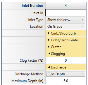
Discharge Data
Discharge Method
Select the discharge method from the drop-down list box. You can develop flows by specifying:
- Range of depths with user-defined number of increments
- Known Q
- Set of user-defined flows
Q vs. Depth
This option will produce a complete rating table with a range of depths at pre-determined Qs, every 0.5 cfs for example. For Q vs Depth, enter the Maximum Depth to be used for the Rating table. The default value is 6 inches (150 mm). Depths will be computed at increasing Q increments shown in the Settings, typically 0.50 cfs until the Maximum Depth is reached. For example, if the Maximum Depth is 6 inches and the Q Increment = 0.50 cfs, Studio Express will compute Depths starting at Q = 0.50 cfs, and then 1.0 cfs, 1.5, 2.0, 2.5 and so on. The Results Grid will populate its rows as needed.
Known Flow Rate
Enter a single known flow rate and Studio Express will compute corresponding depth.
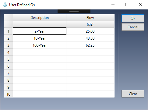
User-Defined Flows
This method allows you to enter a custom set of up to ten unique Q’s. These may, for example, correspond to flows previously determined. Data can also be copied and pasted by right-clicking on the table.
Computing Results
Once you’ve entered your data, click the [Compute] button at the bottom of the input grid.
Studio Express will first do a data check to make sure the inputs are okay. You’ll then be presented with the results.
You can clear the data from the input grid by using the [Clear] button.
Plot Options
Once the results have been computed, you’ll have a variety of ways to view them. You can plot sections (Gutter or Inlet) or a Rating Curve. Sections and Rating Curves (Q vs. Spread) are selected using the toggle buttons at the top left of the canvas.
Sections
You can zoom the section plot(s) by using your mouse wheel. Click the refresh button to reset the plot back to its original scale.


Rating Curve
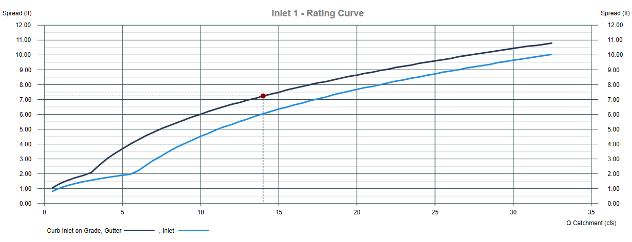
The above plot is a Rating Curve for a Curb Inlet on Grade with a local depression of 3 inches. It plots curves for the spread at the gutter and at the inlet face. The vertical distance between the two is the benefit of the local depression.