This task pertains to the analysis of groundwater mounding and the management of polluted runoff water. The retention and treatment of the initial stormwater runoff, known as the “First Flush”, involves storing it in a retention pond for infiltration. Regulatory standards dictate that a retention pond must have the capacity to contain the first flush volume and gradually release it into the soil within a designated period, usually 24 to 72 hours.

In typical scenarios, this process is achieved by monitoring the amount of water that would seep into the ground at a given infiltration rate, measured in inches per hour. This rate can then be used to calculate the outflow in cubic feet per second from the bottom area of a retention pond. By doing so, the drawdown time can be accurately estimated. This assessment relies on the premise of vertical flow from the basin bottom into unsaturated sediments.
When your retention pond is sitting slightly above a high water table in sandy soils, the analysis is not so simple.
But… when the retention pond is located just above a high water table in sandy soils, ranging from 2 to 8 feet, the situation becomes more complex. As the water table underneath starts to rise, it may eventually reach the bottom of the infiltration basin. This leads to a significant decrease in the rate of infiltration out of the basin. Consequently, the soil becomes saturated, causing vertical infiltration to cease, and forcing the water to move horizontally. This horizontal movement can significantly prolong the drawdown time.

Water in the retention basin exits in two distinct stages.
- Unsaturated Flow – Deals with the rate at which water flows out of a pond vertically through its bottom. Governed mainly by the pond’s bottom area, the height above the water table and the soil porosity.
- Saturated Flow – Stage One saturates the soil and prevents further vertical movement. Water begins to flow laterally… Stage Two. Saturated flow occurs beneath the pond bottom and is governed by the lateral transmissive characteristics of the shallow aquifer.
A recovery time for each stage is computed and their sum total is recognized as the total time of recovery. This analysis is performed in Studio Express Groundwater feature. For unsaturated flow it uses a modified Green and Ampt infiltration equation.
For Saturated flow the software employs the Simplified Analytical Method (SAM) as prescribed by Florida’s St. Johns River Water Management District’s (SJRWMD) environmental resource permitting manual. The methodology is described in detail in Part X of that manual.
SAM was derived from the U.S. Geological Survey (USGS) MODFLOW computer program and requires that filling of the pond with the treatment volume be simulated as a “slug” loading (i.e., treatment volume fills the pond within an hour).
The remainder of this article describes the necessary inputs for producing a retention pond recovery analysis.
How to Perform Groundwater Mounding Analysis
The input criteria have been designed to be concise yet comprehensive. To input data, simply enter the value or choose from the drop-down input box, and then press either [Enter] or the [Tab] key. The following provides a description of the necessary items. After inputting the data, the results can be calculated by clicking the [Compute] button located at the bottom of the input grid.
Inputs are divided into five categories;
- Retention Pond (physical characteristics)
- Groundwater (Impervious layer and water table elevations)
- Unsaturated, Stage 1
- Saturated, Stage 2
- Treatment Volume
While entering data for the first time, the canvas will automatically display a help diagram to assist in your data entry.
Pond Name
Optional but it is a recommended input as it is this label that identifies the Pond on the Ponds List and formal reports.
Retention Pond
It should be noted that this analysis requires rectangular-shaped pond dimensions simply for computational purposes, not because of software restrictions. Thus it requires a single length (L) and width (W) input and the Width is always less than or equal to the Length. Ideally the L/W ratio should be 1, 2, 4, 10 or 100 but your inputs are not restricted to those ratios.
If you have a non-rectangular-shaped pond bottom, then L & W values can be easily determined by taking the square root of the bottom area. Better yet, Studio Express provides a utility that will compute an equivalent Length and Width for any shaped pond. Described in more detail here.
Bottom Elevation
Enter the elevation of the bottom of the pond.
Bottom Length, L
Enter the average length of the pond bottom. This should be the higher of the two L & W values.
Bottom Width, W
Enter the average bottom width. Must be less than or equal to the Bottom Length.
Total Depth
Enter the total depth of the pond. This depth should not exceed the elevation of any overflow weir crests or other outlet structure in the retention pond.
Side Slopes (h:1)
Enter the pond side slope as horizontal to 1 (h:1).
Voids (%)
Enter a void ratio in percent for the pond volume. For example, a stone-filled pond would have a ratio of around 40. A completely open basin would be 100.
Groundwater
Seasonal High GW Elevation
Enter the elevation of the water table at it’s high seasonal value.
Impervious Layer Elevation
Enter the elevation of the lower confining layer. Typically clay, rock or hardpan.
Fillable Soil Porosity, f
Select from the drop-down list box. Values are limited to 0.1, 0.2, 0.3 and 0.4. For fine sand aquifers, f will equal 0.20 or 0.30.
Unsaturated
Vertical Conductivity, Kvs
Enter the average vertical hydraulic conductivity, Kvs, in ft/day. This value will be converted into a Design Infiltration rate, Id, during the calculations as Id = 2/3Kvs/FS.
Factor of Safety, FS
Enter the factor of safety. A common value is 2.0.
Saturated
Horizontal Conductivity, Kh
Enter the average horizontal hydraulic conductivity rate, Kh, in ft/day.
Volume
Treatment Volume
Enter the treatment or water quality volume. A common calculation for this is 0.50 inches of runoff or 1.25 inches times the impervious area, whichever is greater. And then an additional 0.50 inches is added. This volume must be able to fit in the retention pond, obviously.
Computing Results
Once you entered your data, click the [Compute] button at the bottom of the input grid.

Studio Express will first do a data check to make sure the inputs are valid. You’ll then be presented with the results. You can clear the data from the input grid by using the [Clear] button.
Viewing Results
You’ll be presented with an output table and three optional graphic outputs.

Section Plot
The Pond Section plot will look similar to the following.
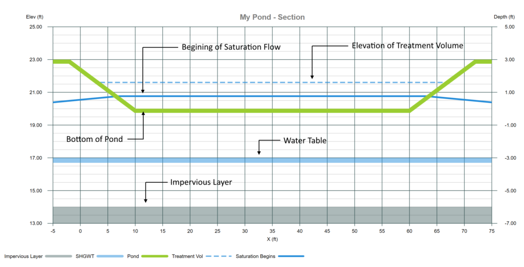
The blue dotted line indicates the elevation in the pond that corresponds to the initial Treatment Volume. Unsaturated flow begins here.
The solid blue line indicates the elevation at which the soil is saturated and vertical infiltration has stopped. The unsaturated recovery time ends at this point and saturated recovery begins. Saturated recovery ends when this line retreats down to the pond bottom.
Results Table

The results are categorized into four main sections.
RECOVERY TIME
The time units will be shown in hours if the Total time is less than or equal to 3 days.
Unsaturated – This is the time up to where the soil is completely saturated and vertical movement ends.
Saturated – Time for the water level to reach the pond bottom. Note that there may be occasions when the entire treatment volume has been fully infiltrated during the first phase, vertical unsaturated flow. When this happens, the Saturated time will be zero.
Total – Equals the sum of Unsaturated and Saturated time.
VOLUME
These volumes can also be viewed on the Stage-Storage plot.
Pond – The total volume available in the retention pond.
Treatment – The inputted Treatment Volume.
Unsaturated – The volume of water that was infiltrated during the unsaturated stage.
Saturated – The remaining volume, i.e., Treatment Volume – Unsaturated Volume.
ELEVATION
These elevations can be viewed graphically on the Stage-Storage Plot.
Top of Pond – The pond bottom plus the pond depth.
Treatment – Elevation corresponding to the Treatment Volume.
Saturated – The elevation corresponding to the Saturated Volume.
CHART
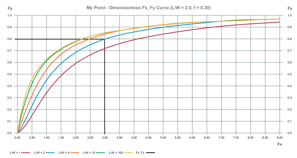
The SAM method was developed by generating a series of runs in the USGS MODFLOW computer program commissioned by SJRWMD. These runs were used to generate a series of dimensionless curves to predict retention basin recovery under lateral saturated flow (Stage Two) conditions. This allowed a complicated numerical procedure to be performed much easier by hand. Thus the “Simplified Analytical Method”.
These curves can be found in the refenced SJRWMD environmental resource permitting manual and are also regenerated in Studio Express using polynomial equations. For documentation purposes they may be viewed by clicking the [Chart Fx, Fy] toggle button. It is from these curves that the Time of Saturation is computed.
Fy – This value is computed first and is the ratio of the (distance from the Pond Bottom to the SHGWT) to the distance from the (Saturated Elevation to the SHGWT).
Fx – Comes from the dimensionless curve for the associated Fy, L/W and f. The Time of Saturation is computed from Fx.
It should be noted that these curves were limited to fillable porosity (f) values of 0.10, 0.20, 0.30 and 0.40. This explains the input limits on the f variable in Studio Express. Within each of these f values are limits to L/W of 1, 2, 4, 10 and 100. However, when Studio Express encounters an L/W ratio 10 percent outside of these values, it interpolates between them. For example, if the inputted L/W is 2.2, the software will use 2.0 because it is within 10 percent. If the L/W is 1.4, then the software will interpolate between the L/W = 1 and L/W = 2 curves. This will be shown on the Fx, Fy plot and will also be indicated in the formal report.