Perform Stormwater Retention Pond Recovery Analysis on Exfiltration Trench
Design Example #3
The following design example demonstrates how to use Studio Express Groundwater feature for estimating recovery time for an exfiltration trench. The infiltration design methodologies for retention systems are also applicable to exfiltration trenches.
Given:
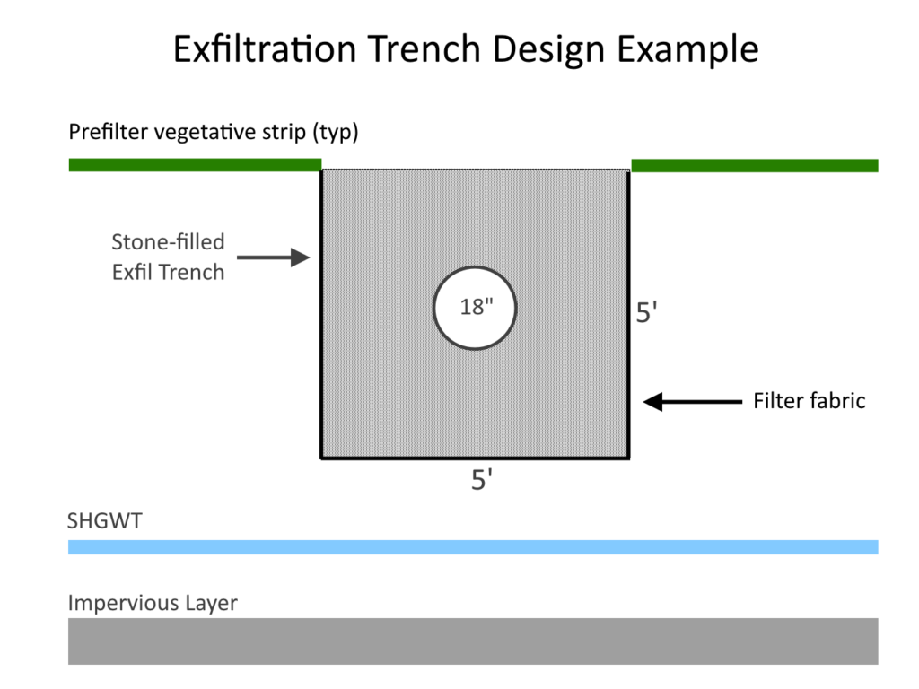
An exfiltration trench is a dug-out trench that includes a conduit, typically a perforated pipe, encircled by stone aggregate. Its purpose is to collect and enable the infiltration of stormwater runoff into the adjacent soil from both the bottom and sides of the trench.
Each instance of rainfall runoff is captured and primarily treated through settling and exfiltration. The presence of a perforated pipe aids in expanding the storage capacity within the trench and facilitates exfiltration by evenly dispersing the runoff along the entire length of the system.
Given the provided inputs, we will calculate the time it takes for the system to recover.
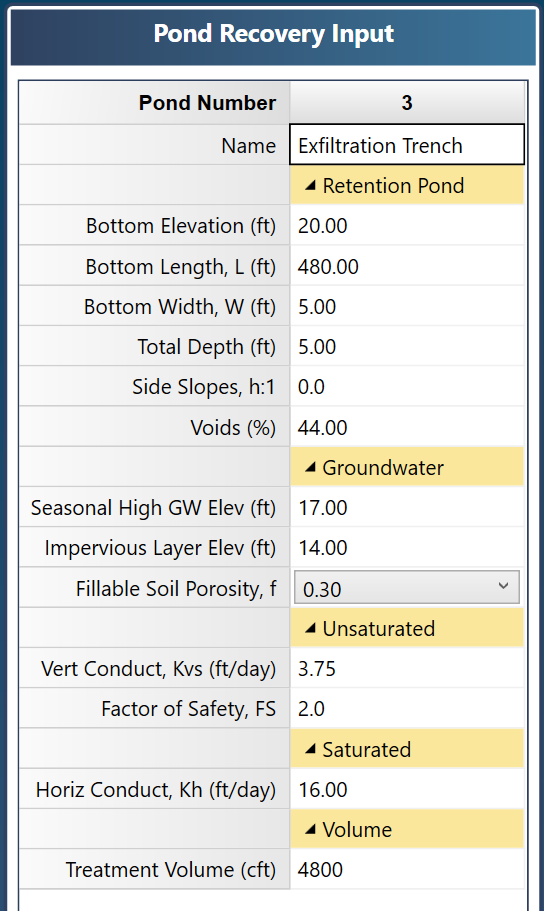
Trench bottom elevation = 20.0 ft
Trench length, L = 480 ft
Trench width, W = 5
Trench depth = 5.0 ft
Side slopes = 0:1
Voids = 44% (details below)
Seasonal high ground water table (SHGWT) = 17.0 ft
Impervious layer elevation = 14.0 ft
f = 0.30 (fillable porosity of surrounding soil)
Kvs = 3.75 ft/day (Vertical)
FS = 2.0
Kh = 16 ft/day (Horizontal)
Treatment Volume = 4,800 cubic feet (based on local drainage authority guidelines)
Compute the Equivalent Voids
Determining the void ratio is a crucial aspect when examining a trench containing a perforated pipe. Although Studio Express Groundwater does not specifically cover trenches with embedded pipes, accurate outcomes can still be achieved by reverse-engineering a void ratio that yields the same volume.
Compute the actual area of the designed section
Area of the pipe, Ap, = PI x Dia2 / 4 = PI(1.5)2 / 4 = 1.77 sqft
Area of trench = V x 5 x 5 = .40(25) = 10 sqft (40% stone voids)
Total Area = 10 – 1.77 x .40 + 1.77 x 1 = 11 sqft
An appropriate void ratio to specify in Studio Express is the total area of the designed trench divided by the open area of the trench (assuming no voids) or 11 / (5 x 5) x 100 = 44%.
Data Entry
Enter this data into Studio Express Input Grid as shown below, and click [Compute].

Below are the results.
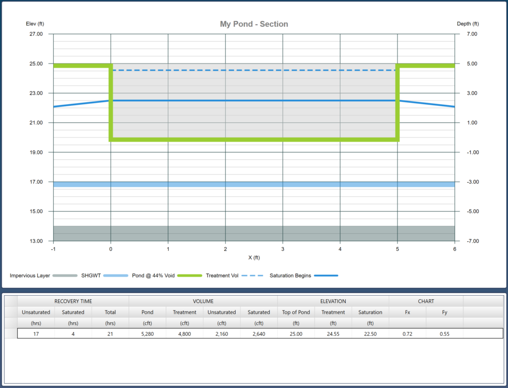
The Infiltration Analysis
Once the Treatment Volume was introduced to this trench, the water elevation rose to 24.55 ft (dotted line). Vertical, unsaturated flow began and later stopped at full saturation. It took 17 hours and used up 2,160 cft of the Treatment Volume. This left 2,640 cft in the trench at a water level of 22.50 ft (solid line). It then took 4 hours for that volume to infiltrate horizontally, until the trench was empty. Total time to recover is 17 + 4 = 21 hours.
Note that L/W = 480/5 = 96. Since 96 is within 10% of 100, the L/W value will be rounded up to 100. Any L/W’s that are not within 10% of 1, 2, 4, 10 or 100 will be not be rounded and Fx will be interpolated between the adjacent charts.
Getting a Printed Report
A final report can now be viewed and printed. Included in this report are detailed calculations to properly document your work. Click the [Reports] button on the Ribbon tool bar and you should see the following:
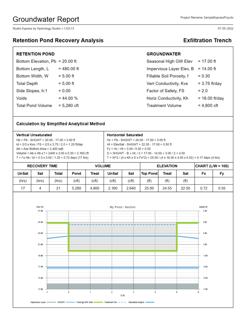
You have the option to incorporate the additional charts available in the Groundwater feature, such as Stage-Storage and Fx-Fy, by simply right-clicking on them and choosing “Export this chart…”. The chart can be saved in various bitmap formats. Furthermore, if viewing any of those charts while generating a report, it will be that chart shown on the report.