The discharges from the outlet structure are determined based on the water surface elevations within the pond. The initial creation of the pond (Step 2) is essential as it allows the program to establish a range of elevations for calculating discharge values, spanning from Stage zero to the maximum height of the pond.
The procedures described below are divided into two categories:
- Culverts & Orifices
- Weirs
Multi-Stage Outlet Structure Options
If the multi-stage option (“Flows through Culvert”) is not checked, each outlet structure is treated independently.
The “Flows through Culvert” option allows you to put structures in series, thereby creating a multi-stage structure. This causes the outflows from that device to route through the Culvert. The structure with the least capacity at any given stage controls the outflow at that stage. The Culvert is always the final outflow device so it does not need a multi-stage option.
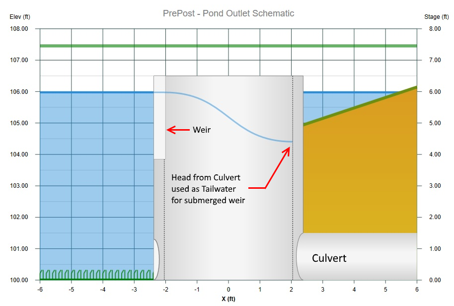
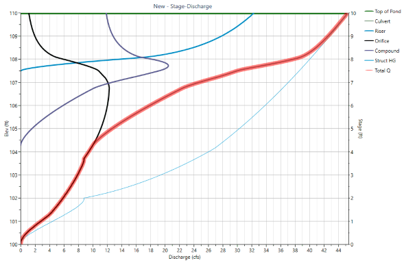
It’s important to note that Hydrology Studio considers the complex interaction between the outlet devices in that the upstream head produced by the Culvert is provided as a tailwater for the secondary, multi-stage devices. The Culvert’s head is the water surface inside of the Riser structure and is depicted by the thin blue line (Struct HG) in the chart below.
In other words, as the Culvert approaches its flow capacity, it begins producing a headwater. This headwater begins to fill up the Riser (upwelling) which in turn reduces the positive head against the Orifice and Weir. As the positive head diminishes, so does the flow contribution from these two devices. Eventually the Riser becomes completely submerged. The secondary Orifice and Weir are disabled with no head, thus no flow. The Culvert at that point controls the total outflow.
Culverts & Orifices
The standard orifice equation is used for culverts and orifices. It’s origin comes from the American Concrete Pipe Association and FHWA Hydraulic Design of Highway Culverts.
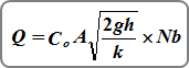
Inlet Control (culverts and orifices)
Q = discharge (cfs)
A = actual flow area (net area when using restrictor plate) (sqft)
h(i) = distance between the inlet water surface and the centroid of the culvert or orifice barrel (1/2 flow depth during partial flow) (ft)
Nb = number of barrels or orifices
Co = orifice coefficient
k = 1
Outlet Control (culverts)
Q = discharge (cfs)
A = actual flow area (sqft)
h(o) = distance between the upstream
and downstream water surface
Nb = Number of barrels
Co = 1
k = 1.5 + [(29n²L)/R¹·³³]
Where:
n = Manning’s n-value
L = culvert length (ft)
R = area/wetted perimeter (ft)
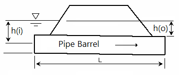
h(i) = inlet control head. h(o) = outlet control head.
During the calculation process, both inlet and outlet control are evaluated. Under inlet control, the discharge depends on the barrel shape, cross-sectional area of the pipe and inlet edge. Under outlet control, the discharge depends on the slope, length and roughness of the barrel. Under outlet control, flow can enter the structure at a faster rate than it can exit. Under Inlet control, it’s harder for water to enter the pipe than exit.
It’s important to note that these are not your typical roadway culverts. In both flow regimes, the loss coefficient, k, is greater than or equal to 1. This stems from the fact that the culvert is in a detention pond where the velocity is zero and thus no approach velocity like you would see at a roadway-type culvert. The entire upstream velocity head of the culvert is converted to static head. Thus 1 x (V^2/2g). In Outlet Control, ke = 1 + 0.5 where the 0.5 represents the entrance loss assuming a square-edged inlet configuration.
Culvert Velocity
The culvert velocity is reported on the Pond Outlets Table next to the Culvert’s Q. This velocity is based on the associated Q and using Normal Depth as computed by Manning’s equation. Velocity = Q / A, where A is the cross-sectional area of Normal Depth. This velocity provides a more useful metric as it pertains to the Culvert’s normal flow at the downstream end or exit which can be used for scour considerations.
Tailwater
When a tailwater (TW) elevation has been entered, it is compared to the pond stage and computes a tailwater head, hTW. If this head is less than the head computed as above (h), then h = hTW.
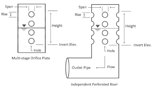
Perforated Riser
This is a special kind of orifice structure as shown below which contains a series of same-sized holes all within a vertical height. This outlet device can take the shape of a single multi-holed plate or an independent riser.
Orifice Plates for Water Quality Volume (WQv) Recommendations
A study performed by the Urban Drainage and Flood Control District, Denver, CO in 2016 resulted in the recommendation of limiting the number of water quality orifices to no more than three. When the number of orifices is limited to three (as opposed to the traditional three per foot of depth), the size of each orifice becomes larger and therefore less prone to clogging.
These orifices should spaced at stage zero, H/3, and 2H/3, where H is the maximum ponding depth of the water quality capture volume (WQv). For example, if the WQv volume produces a depth of 3 feet in your pond, you will want three holes. One at the invert (Stage 0.00); one at Stage 3 / 3 = 1.00; and the third at Stage 6 / 3 = 2.00. The Height value you will enter will be 2.00 plus the hole Rise in feet (meters).
The following formula by McEnroe, 1988 is used to estimate the outflow.
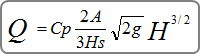
Where:
Q = discharge (cfs)
Cp = 0.61
A = cross-sectional area of all the holes (sqft)
Hs = height (ft)
H = distance between water surface and the Invert Elevation (ft)
Weirs
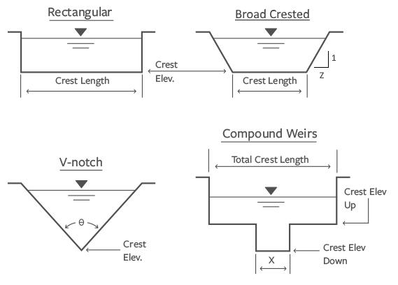
Hydrology Studio uses a standard weir equation for Rectangular, Compound, Cipoletti, Broad Crested & Circular or Box Riser structures.
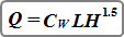
Where:
Q = discharge over weir (cfs)
L = length of the weir crest (ft)
H = distance between water surface and the crest (ft)
Cw = weir coefficient, typically 3.33
Broad Crested with Sloped Sides
Total flow over broad crested weirs with side slopes is computed using the standard weir equation as shown above, plus two times the flow given from the following equation.
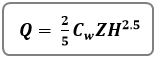
Where:
Q = discharge over side-sloped portion of weir (cfs)
Z = side slope (Z horizontal to 1 vertical) of the weir crest
H = distance between water surface and the crest (ft)
Cw = weir coefficient, typically 3.33
V-notch
V-notch weirs are computed using this equation:
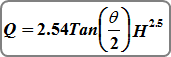
Where: Q = discharge over weir (cfs)
Θ = angle of v-notch (degrees)
H = head on apex of v-notch (ft)
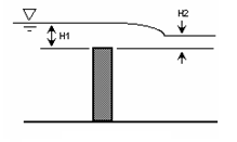
Adjustment for Submerged Weirs
Rectangular, V-notch & Cipoletti weirs can be affected by submergence, i.e., when the tailwater rises above the weir’s crest. This will reduce the flow over the weir crest.
 The equation for the reduction in flow is:
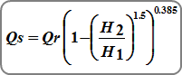
Where:
Qs = submerged flow (cfs)
Qr = unsubmerged flow from standard weir equations
H1 = upstream head above crest (ft)
H2 = downstream head above crest (ft)
An “s” is added as a suffix to discharge values displayed in the Stage-Discharge Table to indicate when flows have been adjusted for submergence. (Not applicable to Riser weir flow.)
Further Reading
Please be sure to visit this page that outlines a recommended, step-by-step procedure for designing multi-stage detention pond outlet structures.