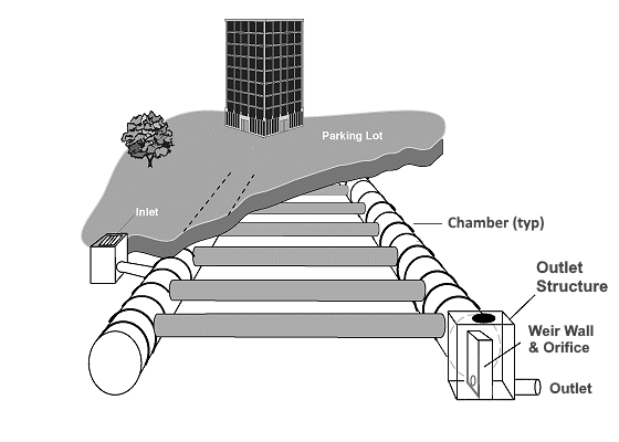
When space is abundant, the most common approach to stormwater retention/detention systems is to design above ground storage ponds. Above ground ponds occupy large amounts of space and can create attractive nuisances, not to mention becoming a breeding ground for insects and other pests. When space is at a premium, underground systems provide an alternative means of stormwater detention storage. They reside underground and free up valuable land above which can still be used for parking lots, green areas or even playgrounds.
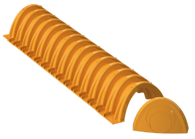
There are numerous solutions to provide underground stormwater detention storage but high density polyethylene (HDPE) pipe often provides the most economical choice. HDPE pipe (Chambers) and associated fittings are easy to install and provide a long service life with minimal maintenance.
Hydrology Studio offers an easy way to setup and model these types of systems. The design process is very similar to that of traditional above-ground designs. It’s the same three-step process of:
- Estimating the maximum required storage
- Creating a Pond (in this case using chambers) to accommodate the required storage
- Designing the Outlet Structure to satisfy discharge requirements
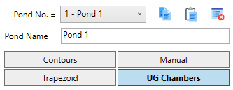
To start, select UG Chambers as the storage type.
You’ll then have two options for your chamber definition:
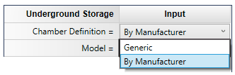
UG Chambers by Manufacturer
This platform allows you to choose from a range of chambers produced by various manufacturers, all of which are integrated into this software. The dimensions and incremental storage capacities will be automatically populated, along with recommended stone encasement sizes. This will simplify your decision-making process for system layout.
Choose this option when you have a clear idea of the specific type of chamber you wish to use. After determining the necessary storage capacity for the pond, you can easily select your desired manufacturer and model from a drop-down menu. The software will automatically populate most of the required fields based on the manufacturer’s specifications. Your only task is to provide the total number of chambers and the number of rows that best meet the project’s site requirements.
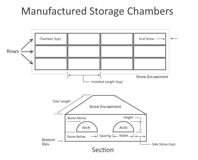
Hydrology Studio provides a comprehensive Plan and Section Layout drawing to support you in this process.
The example layout provided below features a total of 12 chambers arranged in 3 rows.
The inputs for the Manufactured Chambers are simple and straightforward. Perhaps the most difficult decision is the actual chamber selection. As of this writing there are over 40 models from several manufacturers to choose from, and the list is growing.
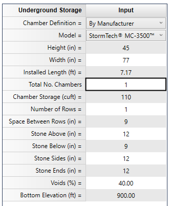
Required Data for Manufactured UG Chambers
Once a model has been selected, its dimensions and bare chamber storage for a single chamber is filled in in the input grid. In addition, suggested dimensions for the stone encasement (spacing, above, below, sides and ends) are filled in. Any of these can be overridden if needed.
Storage per chamber
Enter the bottom elevation of the encasement and click [Apply] to instantly see what the total, single-chamber, storage is. This is displayed on the output table on Row 20. Note that some chambers include end caps that contain storage. From this you can quickly estimate the total number of chambers to use.
How many chambers?
Now specify the total number of chambers; select the number of rows that best suits the site restraints; and you should be very close to a final layout. Adjust any or all parameters as needed.
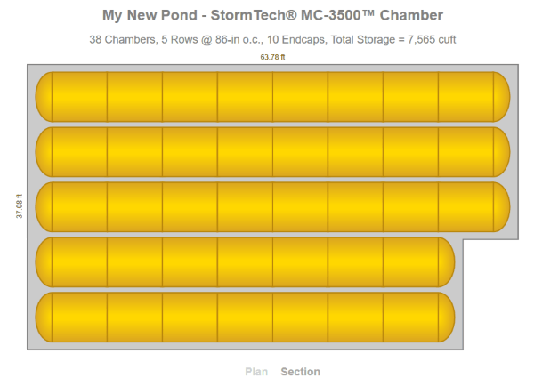
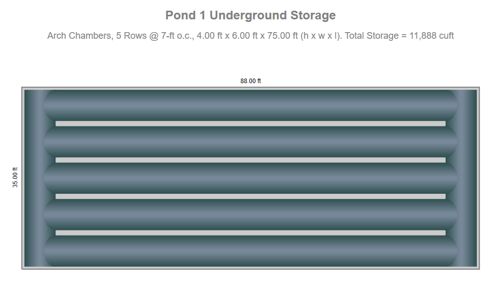
Click on the Layout Chart radio button to view a Plan and Section of your chamber layout as shown below.
Following are descriptions of the required inputs.
Model
Select a chamber model from the drop-down list.
Chamber Height, Width and Length
These values are read-only and will be filled-in based on the Model selected.
Total No. Chambers
Enter the total number of individual chambers. In the Plan view shown above, there are 38 chambers.
Chamber Storage (read only)
The total storage for the number of chambers is displayed and is read-only. This is the bare chamber storage. No end cap storage or stone is included in this.
Number of Rows
Enter the total number of rows. The Plan view diagram shows 5.
Space Between Rows
This will typically be filled in based on the manufacturer’s recommendation but can be overridden.
Stone Above, Stone Below
These will typically be filled in based on the manufacturer’s recommendation but can be overridden.
Stone Sides, Stone Ends
These will typically be filled in using a default of 12 inches and can be overridden.
Voids (%)
Refers to the Encasement stone only, not the Chamber. This value defaults to 40. It allows for the reduction in storage due to a stone-filled encasement.
Bottom Elevation
Enter the elevation of the encasement bottom.
Click [Apply] when finished. Then click the [Next] button to proceed to Step 3 – Outlets.
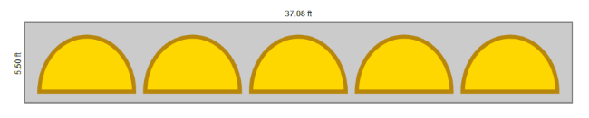
Click on the Layout Chart radio button to see a plan and section view of your chambers. Below is a sample Section view.
Generic Chambers
This choice offers you the most flexibility in chamber shapes, sizes and dimensions. Here you can enter your own data as well as specify headers and stone encasement dimensions.
This option should be utilized when you require a specific design or configuration of an underground chamber that is not available through the Manufacturer option mentioned earlier. It is particularly advisable to choose this option for box-shaped chambers or modules that lack pre-defined dimensions or when numerous configurations are possible.
You should also consider using the software’s Trapezoid shape for these type of systems, instead of UG Chamber, where a void input may be required to account for interior walls or vertical supports, etc.
You can specify underground storage chambers in the shape of circular, arch or rectangular vessels laying either flat or on a slope. Headers as well as a stone encasement are also optional. Hydrology Studio will automatically calculate storage volumes for you based on a given chamber size, shape, slope, length and stone encasement properties.
Note that the Generic inputs will differ somewhat from the Manufactured Chamber inputs. For example, Rise and Span are entered in feet (m) rather than inches (mm). You will also enter the entire length of a row, or barrel as it’s called here, rather than the length of an individual chamber section.
To start, select the UG Chambers button. Then select “Generic” as the Chamber Definition.
Then double-click the Invert Elevation Down input on the input window.
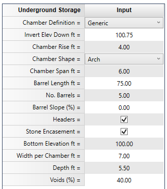
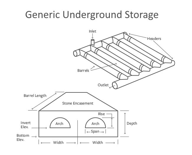
Required Data for Generic Chambers
The following is a description of each of the required input items. Click the Help option button at the top of the input table to view a help diagram.
Invert Elevation Down
Enter the elevation at the lowest point in the chamber. If an encasement is not used, this will be the elevation at stage zero.
Chamber Rise
Enter the diameter or height of the of the chamber vessel in feet (m).
Chamber Shape
Specify Arch, Circular or Box.
Chamber Span
Enter the width of the chamber vessel in feet (m).
Chamber Length
Enter the length, single barrel, of the chamber in feet (m).
No. Barrels
Enter the number of chamber rows or barrels.
Barrel Slope (%)
Enter the slope of this pipe in percent.
Headers
This option will add connecting header chambers at the upstream and downstream ends. They are assumed to have the same shape and size as the primary chambers. Check the box to add headers.
Stone Encasement
Check the corresponding box to indicate stone encasement is being used. If checked, the following inputs apply to the Encasement only, not the Chamber.
Bottom Elevation
Enter the elevation of the encasement bottom. This must be below or equal to the chamber Invert Elevation Down.
Width per Chamber
Enter the encasement width for a single barrel. Must be greater than or equal to the chamber Span. The total encasement width will be computed as (Width per Chamber x No. Barrels). For example, to achieve a 6-inch spacing between chambers, enter the Span plus 0.5 feet.
Depth
Enter the depth of the encasement in feet (m).
Voids (%)
Refers to the stone encasement only. This value defaults to 40. It allows for a reduction in storage due to a stone-filled encasement.
Click [Apply] when finished. Then click the [Next] button to proceed to Step 3 – Outlets.
Click on the Layout Chart radio button to see a plan and section view of your chambers. Below is a layout with 5 barrels including Headers and Encasement.
Using the Interactive Tool
This will sure become your most favorite and productive way to fine tune your Storage Chambers. This tool contains buttons as shown below and basically allows you to edit most of the input items without having to type their values. Your edits will be applied automatically. You’ll see instant results on your output table, Layout Charts and Stage Vs. Storage graphs.

Here’s how it works: Put your cursor on any input item, for example, Total No. Chambers. Then click on either the Arrow Up or Arrow Down buttons. This will increase or decrease the number of chambers by 1.
The default increment is typically set to 1. It is 0.01 ft. for the Bottom Elevation. Holding the [Shift] key down increases the increment to 0.1 ft. Holding the [Ctrl] key down makes the increment 1. Certain inputs are not adjustable using the Interactive Tool. For example, Voids (%). In these cases, the the Interactive tool will show to be disabled or beep.
Stage-Storage Chart
You can quickly view a chart of the Stage-Storage by clicking the Stage-Storage radio button.
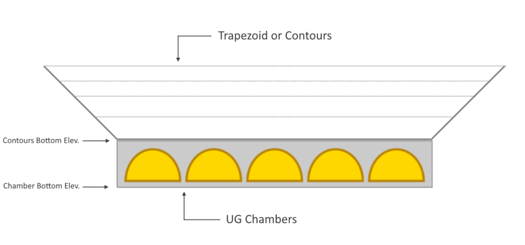
Stacking Storage Types
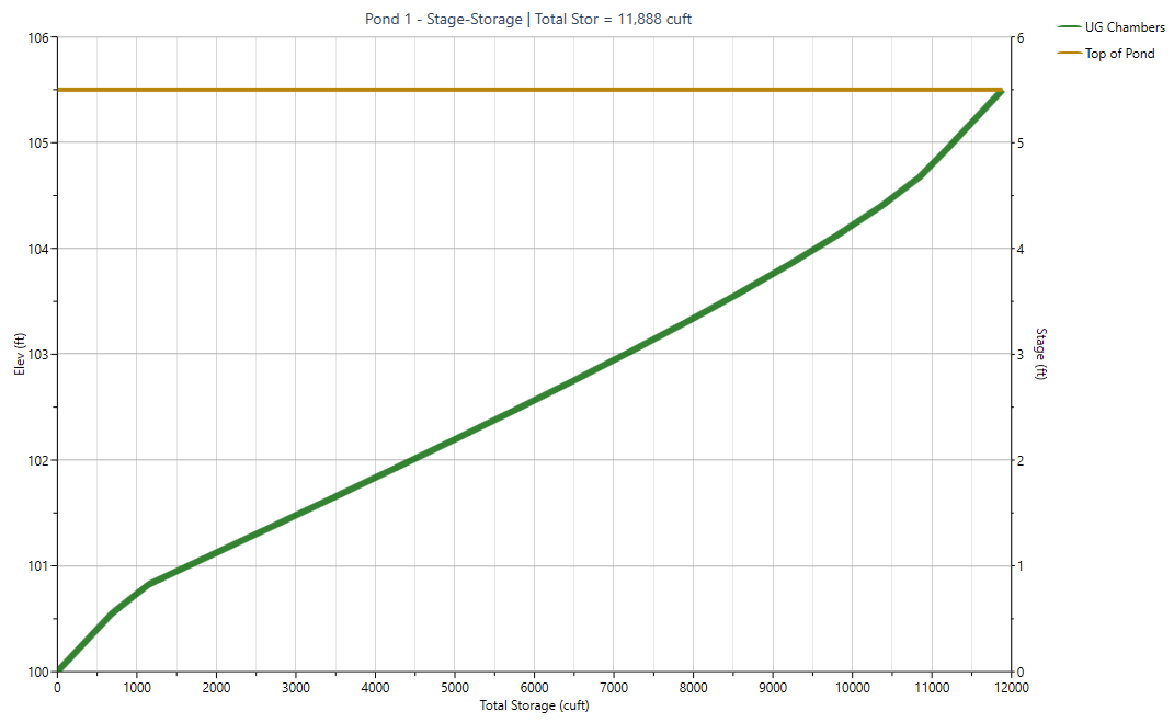
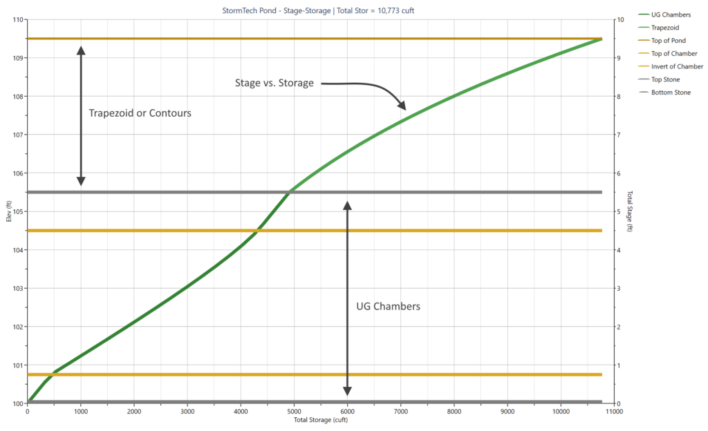
Storage types can be stacked on top of each other in Hydrology Studio. This can be very useful when you want to utilize the storage in an area above your UG Chambers, for example a parking lot. Below is an example of creating a pond by first adding your UG Chambers and then adding a Trapezoid or Contours type.
Below is the corresponding stage vs. storage curve.
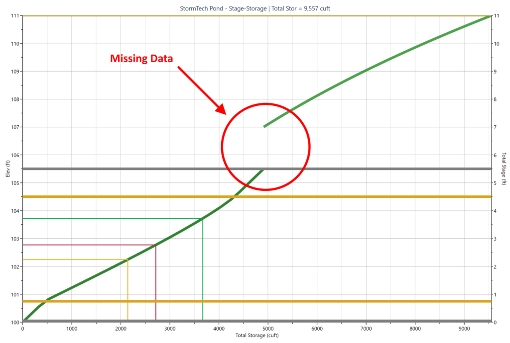
Avoid Gaps in Your Stage Storage Curve
Be sure to set the bottom elevation of the top storage equal to the top of the bottom storage. In other words avoid empty gaps between the two storages as shown below.