Animated flow paths are streamlines that indicate the path of flow between your pond and the outflow culvert in multi-stage outlets as well as stand-alone culverts. These paths are drawn between orifices, weirs, restrictors, exfiltration, etc. all the way through your culvert giving you a clear visual picture of how and where the inflow/outflow is moving. Flow paths will help confirm your multi-stage outlet structure is set up the way you expect by providing a connectivity check.
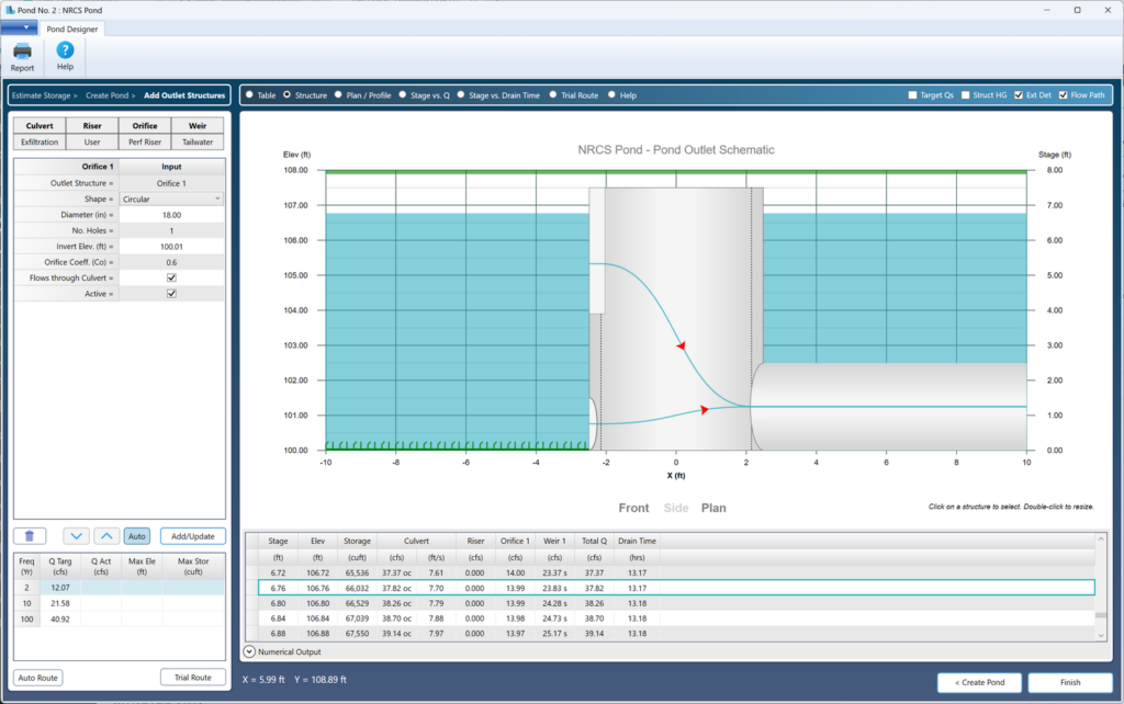
The Flow Paths feature is activated via a checkbox on the toolbar above the Structure schematic.

Select any row on the Trial Route results table or from the Numerical Output Expander table to see corresponding flow paths. If the Numerical Output table is expanded, only flow paths from that table can be shown. Collapse the Numerical Output table to view those from the Trial Route table.
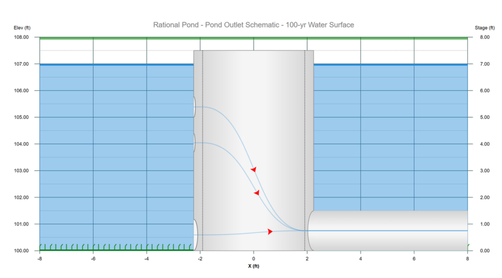
The most informative flow paths will be shown on the Side view. They are also shown on the Plan view. Only Exfiltration flow paths are shown on the Front view.
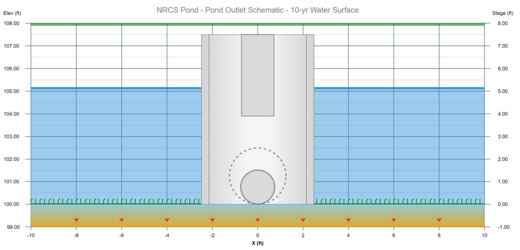
The Flow Paths feature will also indicate when the flow from a device has been diminished due to high structure HG as shown below. In these cases the flow path lines will be dashes and there will be no animation arrows.
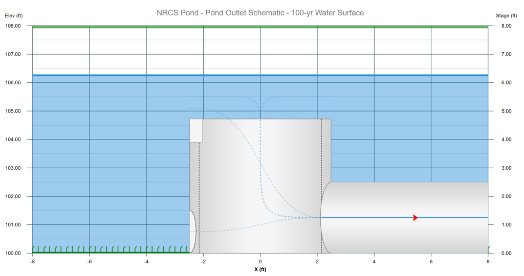
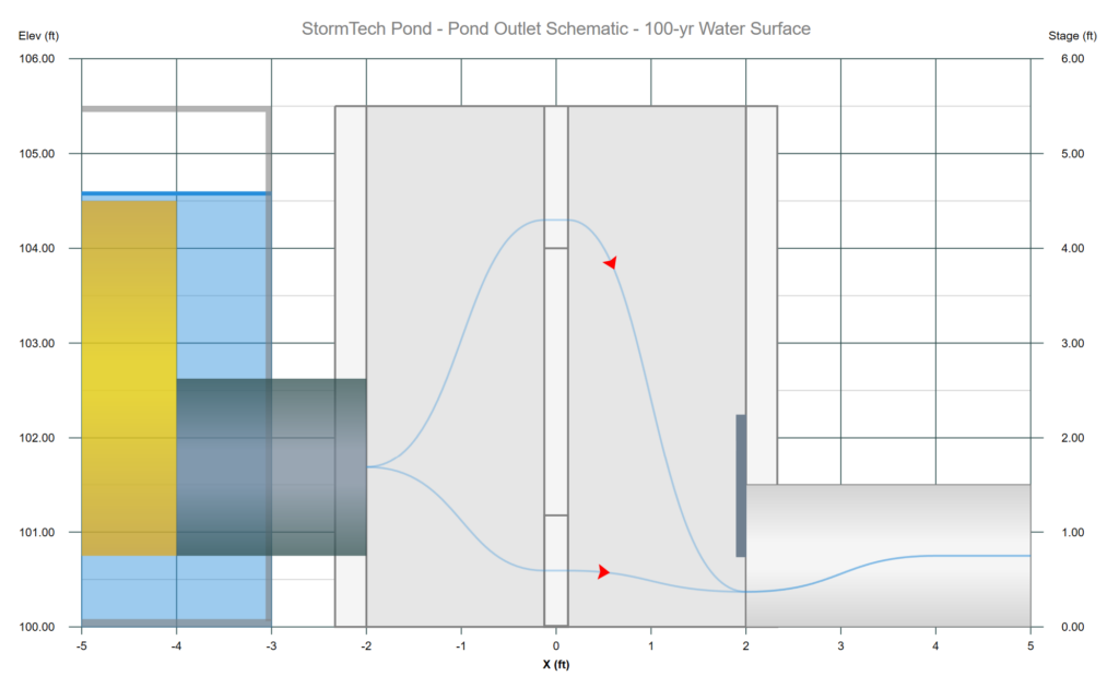
Below is a Side view of an underground chamber with an Orifice, Weir and Restrictor Plate on the Culvert.