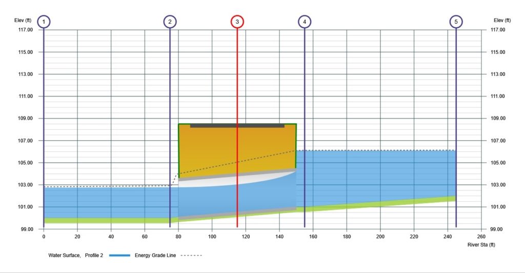
Channel Studio computes energy losses, caused by structures such as culverts, in three parts, similar to the procedures for bridge crossings. The layout of cross sections, the use of the ineffective areas, the selection of loss coefficients, and many other aspects of bridge analysis apply to culverts as well.
The first part consists of losses that occur in the reach immediately downstream from the structure, where an expansion of flow takes place. The second part consists of losses that occur as flow travels into, through, and out of the culvert. The last part consists of losses that occur in the reach immediately upstream from the structure, where the flow is contracting towards the opening of the culvert.
See Working With Culverts for further discussion on locating culvert sections in your model.

Why Culvert Modeling Can Be Difficult
Channel Studio follows calculation procedures described in HEC-22 and HDS-5. Culverts are complicated. Their analysis is difficult and often times confusing. Their flow regimes change with seemingly little reason. Their barrels may flow full or partly full but full flow throughout their length is rare. Generally at least part of their length is in partial flow. The upstream end may be totally under water while underneath, the barrel is in supercritical flow ending downstream in subcritical flow. Raise the tailwater a little and the entire flow regime changes to full.
Channel Studio sorts out these hydraulic anomalies by using time-tested methods and some sophisticated algorithms. This chapter outlines those methods. It starts with an overview of a puzzling concept… Inlet and Outlet Control.
Inlet and Outlet Control
Culverts flow under two regimes:
- Inlet Control
- Outlet Control
Inlet control implies that it is more difficult for water to get in the pipe than it is to get through it. During outlet control, it is more difficult for flow to get through the barrel than it is getting inside of the barrel.
Inlet control is a lot like traffic going from a four-lane highway into a two-lane tunnel. As the traffic nears the tunnel, it must squeeze together causing a traffic jam that affects the cars approaching the tunnel. Once in the tunnel, traveling is easier and traffic speeds up. You’ll find that culverts often flow in partial depth throughout its barrel while under inlet control. Traveling is easier because most of the cars are still trying to get in the tunnel.
If, on the other hand, there was an accident inside of the tunnel, traffic would slow down even more after entering. Traveling is more difficult. This is outlet control.
Inlet control is largely influenced by the entrance geometry of the pipe such as edge configuration, pipe area and shape. Outlet control is influenced most by n-value (barrel roughness), pipe area, shape, length and slope.

So how does one determine the flow regime of a culvert? The solution is to compute the hydraulic profile assuming both exist, and then selecting the one that produces the highest headwater, Hw.
Calculation Procedure
Once a water surface is computed inside the culvert at the downstream end, the program then performs the energy based, Standard Step calculations through the culvert until the water surface and energy are obtained inside the culvert at the upstream end. The last step is to add an entrance loss to the computed energy to obtain the upstream energy (Hw) just outside of the culvert. It is here that both solutions for inlet control and outlet control are compared. The highest is used for Hw.
The newly computed energy grade line (EGL) is then used as the starting EGL for the next upstream section. Its starting HGL is obtained by back-calculating the water surface that corresponds to the EGL.
Please see the following articles for detailed calculation procedures.
