This task allows you to model single open channels and closed pipe sections, with a variety of shapes and configurations. Quickly find the full-flow capacity as well as other flows through a range of depths. It provides graphs, grid-style numerical outputs, a rating table and formal printed reports. Studio Express also includes the ability to design channel widths, pipe spans and diameters based on a single known Q.
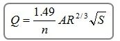
An open channel is defined as a conduit for flow which has a free exposed surface. They typically include channels, streams, natural or man made or highway gutters and ditches. When water flows in a uniform channel it ultimately reaches and maintains a constant velocity and depth called Normal depth. The energy grade line (EGL) parallels the water surface (hydraulic grade line) because the energy loss is exactly compensated for by gravity. Studio Express uses Manning’s equation to compute Normal depth.
At normal depth, the slope of the invert of the channel or pipe is equal to the slope of the EGL… the S term in Manning’s Eq.
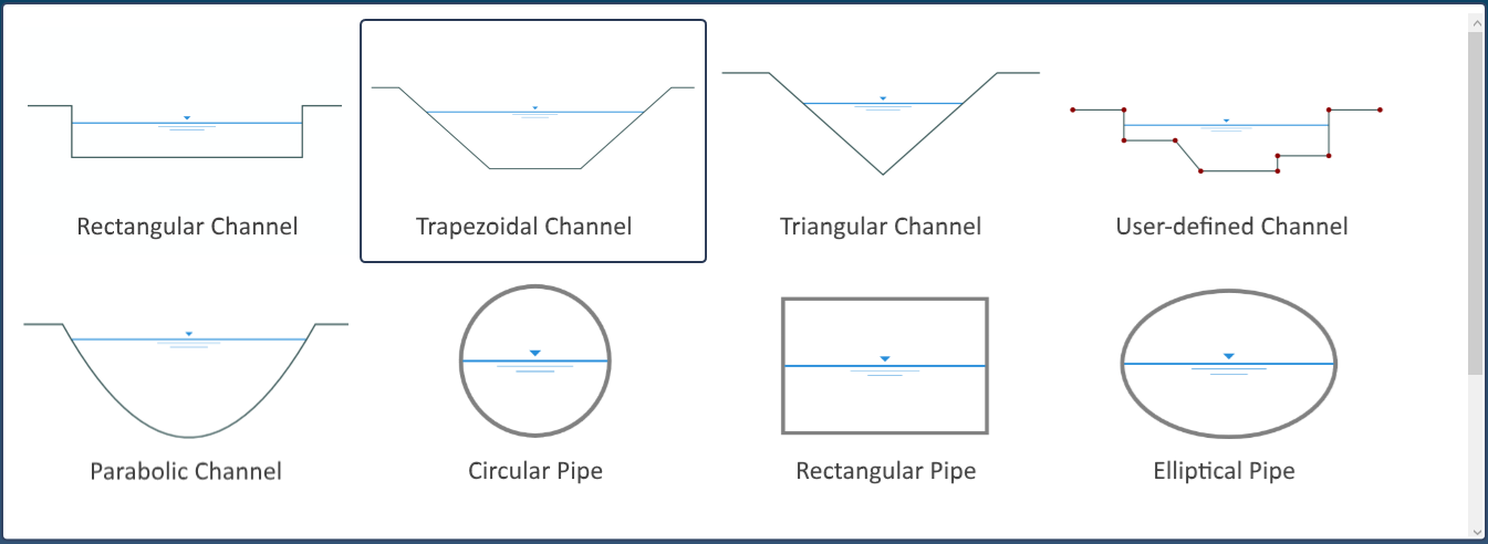
The following channel shapes are available:
- Rectangular
- Triangular
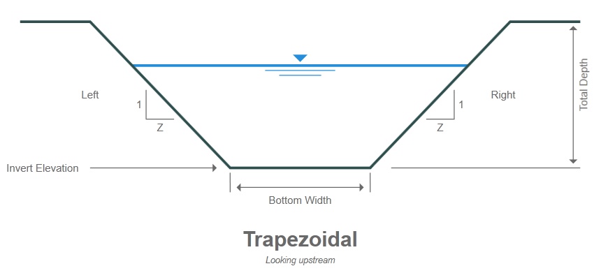
- Trapezoidal
- User-defined (Enter user-defined station, elevation points)
- Parabolic
The following pipe shapes are available:
- Circular
- Rectangular
- Elliptical
- Arch
It is assumed that these channels and pipes are uniform, have a constant shape, slope and flow rate. N-values are constant but can vary across User-defined sections. Studio Express quickly calculates:
- A rating table of Q vs. Normal depth based on a range of flow rates
- Normal depth from a single known Q
- Flow from a user-defined depth
Channel & Pipe Input Requirements
The input requirements are designed to be minimal but thorough. To enter data, type in the value or select from a drop-down input box, and press [Enter] or the [Tab] key. Following is a description of those required items. Once the data is input, results are computed by clicking the [Compute] button at the bottom of the input grid.
Data is divided into two categories;
- Channel / Pipe (physical characteristics)
- Discharge (flows)
Following is a description of each. Please note that size inputs for channels will be in feet (meters) while pipe size inputs are in inches (mm).
While entering data for the first time, the canvas will automatically display help diagrams to assist in your data entry and the input grid will show only required data items.
Channel Name
Optional but it is a recommended input as it is this label that identifies the section on the Channels List and reports.
Channel / Pipe Data
Section Type
Select the type of channel or pipe from the drop-down list box or visually select from the Canvas. (Scroll down on the canvas to see all of the available shapes).
Inputs needed depend on the channel type selected. Below is a description of all inputs.
Bottom Width
Enter the width of the channel bottom in ft (m).
Top Width
Enter the total distance across the top of a Parabolic channel.
Side Slope Left & Right (z:1)
Enter the left and right side slopes, z horizontal to 1 vertical, for the channel.
Total Depth
Enter the total depth of this channel as the distance from the invert to the top.
Diameter
Enter the diameter of a circular pipe section in inches (mm).
Span
Enter the span or width of the rectangular, elliptical or arch pipe section in inches (mm).
Rise
Enter the rise or height of rectangular, elliptical or arch pipe section in inches (mm). There are no design options for this input.
Invert Elevation
Enter the elevation of the channel or pipe invert. This will be automatically extracted when using User-defined section.
Slope (%)
Enter the slope of this channel or pipe as a percent, feet (m) / 100. No design option.
Manning’s n-value
Enter Manning’s n-value for this section. For User-defined sections, click the [Define] button to open the Sta Elevation input screen where you can enter varying n-values.
User-Defined Channels
Studio Express allows you to enter up to 50 station & elevation points to describe a channel section. In addition, each of these points can hold a unique n-value.
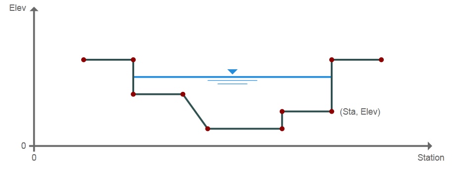
To use this channel feature, select User-defined as the Section Type from the drop-down list or from the canvas. Next click the [Define] button to open the User Defined Channel screen.
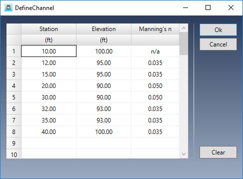
A user-defined section is described by entering points containing offset stations, elevations and related n-values. N-values apply between the current point and the previous point. Point No. 1 does not require an n-value. The n-value entered at Point No. 2 describes the roughness between Points 1 and 2. The n-value at Point 3 is the roughness from 2 to 3, and so on. In the table shown above, the n-value between Station 15 and 20 is 0.050.
Station
Enter the station for this point from the leftmost side as looking upstream. This is the distance from a baseline. Zero is suggested for Point No. 1.
Elevation
Enter the corresponding elevation for this point.
N-value
Enter the corresponding roughness coefficient from the previous point up to this point. Always zero for Point No. 1.
Inserting and Deleting Rows
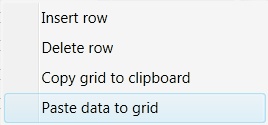
You can insert and delete rows by selecting any row and right-clicking.
Copy and Paste Data
Similarly, you can copy the entire grid to the Windows Clipboard as well as paste previously copied data, for example, from a spreadsheet.
Discharge Data
Discharge Method
Select the discharge method from the drop-down list box. You can develop flows by specifying:
- Range of depths with user-defined number of increments
- Known Q
- Known depth
- Set of user-defined flows
Q vs. Depth
For Q vs Depth, enter the number of increments or depth values to be used for the Rating table. The default value is 10. The total cannot exceed 100. For example, if the Total Depth is 5 and the Increments = 10, Studio Express will compute Q’s for each 5/10 or every 0.5 feet of depth. The Results Grid will populate with 10 rows beginning at 0.5 feet up to 5.0.
Known Flow Rate
Enter a known flow rate and Studio Express will compute a corresponding normal depth. Use this option when invoking design functions described above.
Known Depth
Enter a known depth and Studio Express will compute a corresponding discharge. This value must be <= Total Depth, Diameter or Rise.
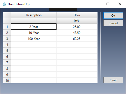
User-Defined Flows
This method allows you to enter a custom set of up to ten unique Q’s. These may, for example, correspond to flows previously determined. Data can also be copied and pasted by right-clicking on the table.
Computing Results
Once you’ve entered your data, click the [Compute] button at the bottom of the input grid.
Studio Express will first do a data check to make sure the inputs are okay. You’ll then be presented with the results.
You can clear the data from the input grid by using the [Clear] button.
Plot Options
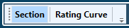
Once the results have been computed, you’ll have a variety of ways to view them. You can plot sections or a Rating Curve. Sections and Rating Curves are selected using the toggle buttons at the top left of the canvas.
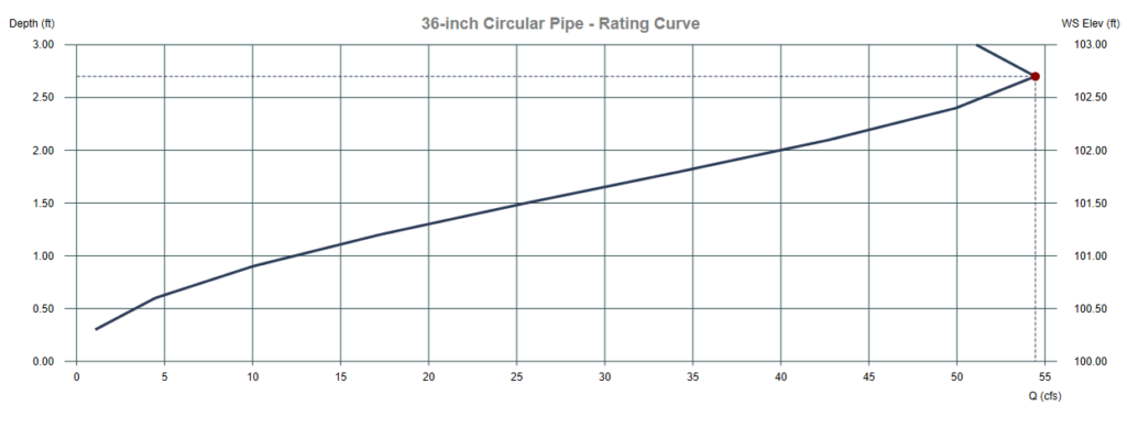
Finding Full-Flow Capacity
Studio Express can provide flows throughout a range of incremental depths or can simply compute the flow at full depth. In both cases you will get the resulting “Full Flow Capacity”.
It’s important to note that closed pipes can convey more flow at depths slightly less than full. The rating curve above indicates that a 36-inch circular pipe has a full flow (full depth) capacity of 51.10 cfs but it can carry 54.45 cfs at only 32.4 inches of depth.
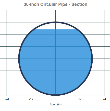
As one can easily observe, the wetted perimeter (Wp) increases disproportionately with increasing cross-sectional area near the top. This increase in Wp decreases the R term in Manning’s equation as shown below, thus decreasing the flow capacity at full depth.